Frame Relay
Frame Relay is a scalable WAN solution that is often used as an alternative to
leased lines when leased lines prove to be cost prohibitive. With Frame Relay,
you can have a single serial interface on a router connecting into multiple
remote sites through virtual circuits.
Concepts and Terminology
You should be familiar with many terms when working with Frame Relay. The
following sections introduce you to these terms and their definitions.
Virtual Circuits and Network Design
Your virtual circuits can be either permanent or switched. A permanent virtual
circuit (PVC) is always connected and, once up, operates very much like a leased
line. A switched virtual circuit (SVC) is established only when it is needed. Of
these two, PVCs are much more common.
DLCI
Circuits are identified by data-link connection identifiers (DLCI). DLCIs are
assigned by your provider and are used between your router and the Frame
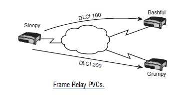
Relay provider. In other words, DLCIs are locally significant. My example will show that there
are three routers named Sleepy, Grumpy, and Bashful.
The Sleepy router is connected to a Frame Relay provider that provides
permanent virtual circuits to both the Bashful and Grumpy routers. DLCI 100
defines the PVC to Bashful, and DLCI 200 defines the PVC to Grumpy.
Although it is not shown in the figure, Bashful and Grumpy will likewise have
DLCIs to define their PVCs back to Sleepy.
As an analogy, DLCIs are like shipping docks. If you work for a shipping company,
you might have several ships attached to docks that are each going to a different destination.
When you have a package to ship, you just need to take it to the ship headed
for the destination. It is the captain’s job to know how to reach the destination.
DLCIs are like these docks. They are significant only on your side. You send
your packet out the relevant DLCI, and the provider’s job is to figure out how
to get that frame to its destination.
LMI
Behind-the-scenes is a little helper called the local management interface (LMI)
that works as a status enquiry and reporting message. LMI messages are sent
146
Chapter 7: Introduction to Wide-Area Networks
between your router and the Frame Relay provider’s equipment to verify and
report on the status of your PVC. The three possible states that your PVC can be
in are
.
Active—Active is good. Active means that everything is up and operational..
Inactive—Inactive is bad. Inactive means that you are connected to yourFrame Relay provider, but there is a problem with the far-end connection.
The problem is most likely between the far-end router and its connection
to the Frame Relay provider. You should contact your provider
to troubleshoot the issue.
.
Deleted—Deleted is also bad. Deleted means that there is a problembetween your router and the Frame Relay provider’s equipment. You
should contact your provider to troubleshoot this issue.
Because of the frequency of LMI messages sent between your router and the Frame
Relay provider, LMI is also used as a keepalive mechanism. Should your router stop
hearing LMI messages it will know that there is a problem with your PVC.
There are three types of LMI. These can be manually configured (discussed
later in the configuration section) or, with IOS 11.2 and higher, can be autodetected.
The three types of LMI are
.
Cisco.
ANSI.
Q933ACIR
The committed information rate (CIR) is the guaranteed rate at which you are
allowed to pass data for a particular PVC. When ordering a PVC, you will
request a local access rate (the bandwidth of the physical connection) and the
CIR for a PVC. For example, you may order a T1, which has a local access rate
of 1.544Mb for the Sleepy router, and a CIR of 128K for the PVC to Bashful,
and a CIR of 512K for Grumpy.
BECN and FECN
Frame Relay is generous with its bandwidth. If there is no congestion on your
link, you are allowed to burst above the CIR rate. Any traffic sent above your
CIR is marked as being Discard Eligible (DE) and, in the event of congestion,
will be dropped.
When congestion does occur, congestion notification messages are sent out to
notify both the sending and the receiving routers that congestion has occurred
and that they should slow down their transmission rates. A Backward Explicit
Congestion Notification (BECN) is sent back to the sender and a Forward
Explicit Congestion Notification (FECN) is sent forward to the destination to
notify them of congestion.
A BECN message is only sent back to the source when the destination sends a
frame back. Because the provider must wait for a message to return in order to
set the BECN bit in the frame header, the FECN bit is sent to the destination
to request some traffic to be sent back in the reverse direction. Without this, the
source might never know that congestion has occurred.
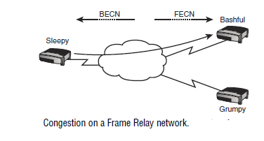
In the next figure, traffic is congested going from the Sleepy router to the Bashful
router. A FECN is sent to the Bashful router, and a BECN is sent back to the
Sleepy router.
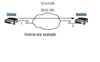
Inverse-Arp
Frame Relay needs a mechanism to map Layer 3 addresses with Layer 2 Frame
Relay DLCIs. This can be done through a static map command (shown later in
the configuration section) or through inverse-arp. Just like Ethernet ARP,
inverse-arp is used to map a Layer 3 address to a Layer 2 address. However,
Ethernet ARP maps an IP address to a MAC address and inverse-arp works to
map an IP address (or other protocol) to a DLCI.
In the next figure Sleepy will need a Layer 3 to Layer 2 map to connect to Bashful,
which has IP address 10.0.0.2. Using inverse-arp, Sleepy will automatically
create a map telling it to use DLCI 100 to get to IP address 10.0.0.2.
NBMA
Frame Relay is a nonbroadcast multi-access (NBMA) medium, which means
that broadcast traffic is not allowed to traverse Frame Relay traffic. There are
ways, however, to circumvent the NBMA nature of Frame Relay to allow broadcasts
to cross the Frame Relay cloud. These are discussed in the configuration
section.
The Split Horizon Problem
The split horizon rule (described in Chapter 10, “Basic Routing”) states that a
route learned on an interface should not be advertised back out that same interface.
This poses a problem in NBMA networks where multiple circuits can connect
to a single interface in a hub-and-spoke topology.
Hub-and-spoke topologies are commonly used to connect multiple branch
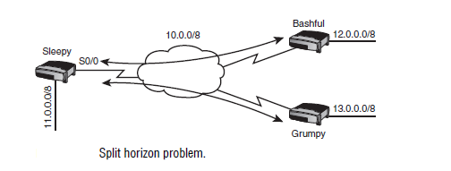
offices to a headquarters office. For example, in Figure 7.7, the Bashful and
Grumpy routers have circuits to the Sleepy router but not to each other. In this
example, Sleepy is operating as the headquarters office. When Grumpy advertises
its 13.0.0.0/8 network to the Sleepy router, it is sent into serial 0/0, but the
Sleepy router is not allowed to send it back out serial0/0. This causes a problem
because serial0/0 is also connected to the Bashful router. As a result, the Bashful
router will never know about the 13.0.0.0/8 network.
You have four options to get around the split horizon problem:
.
Disable split horizon with the no ip split-horizon command. If youare not careful, this could create a loop.
.
Have a fully meshed topology where every router has a PVC to everyother router. This can get expensive.
.
Use static routes instead of dynamic routing protocols. This is not a scalablesolution.
.
Use subinterfaces. This is your best option.Subinterfaces
A
subinterface is a subset of an existing physical interface. As far as the router isconcerned, the subinterface is a separate interface. By creating subinterfaces,
each circuit can be on its own subnet.
There are two types of subinterfaces:
.
point-to-point—This maps a single IP subnet to a single subinterfaceand DLCI.
.
multipoint—This maps a single IP subnet to multiple DLCIs on asubinterface.
Of these two, only point-to-point subinterfaces address the issue of split horizon.
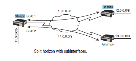
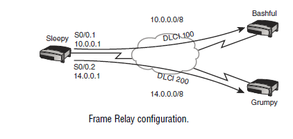
In Figure 7.8, subinterfaces are used on the Sleepy router. Subinterface serial0/0.1
is connected to the Bashful router and subinterface serial0/0.2 is connected to the
Grumpy router. Now when Grumpy advertises the 13.0.0.0/8 network to Sleepy, it
is sent to the subinterface. Sleepy can forward that information on to the Bashful
router because the Bashful router is connected to a different subinterface—a logically
(but not physically) different interface.
Configuration
Configuring Frame Relay involves the following steps:
.
Changing the encapsulation for Frame Relay.
Configuring the LMI type (optional for IOS 11.2 or higher).
Configuring the Frame Relay map (optional unless you are usingsubinterfaces)
.
Configuring subinterfaces (optional).
If using a point-to-point subinterface, configuring your DLCIChapter 7: Introduction to Wide-Area Networks
To begin, select the Frame Relay encapsulation on the interface. There are two
types of Frame Relay encapsulations: Cisco and IETF. Cisco is the default. The
syntax to set your encapsulation is
encapsulation frame-relay
[ietf]Next, you can configure the LMI type. The three LMI types are Cisco, Ansi,
and Q933a. For IOS 11.2 and higher, the LMI type is automatically detected.
For earlier IOS versions, enter the following command under the interface:
frame-relay lmi-type
[cisco | ansi | q933a]The third option, configuring a static Frame Relay map, is optional unless you
are using subinterfaces. The Frame Relay map will map a Layer 3 address to a
local DLCI. This step is optional because inverse-arp will automatically perform
this map for you. The syntax for a Frame Relay map is as follows:
frame-relay
map protocol address dlci [broadcast] [cisco | ietf]ption
Protocol Layer 3 protocol such as IP or IPX.
Address The Layer 3 address of the remote router (such as an IP address or IPX
address).
DLCI Your local DLCI defining your PVC to the remote router.
Broadcast Optional, this allows for broadcasts and multicasts to traverse your
Nonbroadcast Multiaccess (NBMA) Frame Relay network.
Cisco | IETF Optional, this allows you to change your Frame Relay encapsulation per
DLCI.
For example, if you were connected to another router using DLCI 100 and the
router had the IP address of 10.0.0.2, your Frame Relay map statement would be
Router(config-if)#
frame-relay map ip 10.0.0.2 100If you want to use a routing protocol across your Frame Relay network, you will
need to add the keyword
broadcast to the end of this command. Routing protocolsuse broadcasts and multicasts by default, and Frame Relay does not enable
broadcasts and multicasts without the use of the broadcast keyword. If you are
using inverse-arp to create your maps for you, inverse-arp assumes that you
want to use routing protocols and adds the broadcast feature for you.
Frame Relay
151
If you are using a routing protocol in a hub-and-spoke topology, you will probably
want to use subinterfaces to avoid the split horizon problem. To configure a subinterface,
remove the IP address off the main interface and put it under the subinterface.
Configuring a subinterface involves assigning it a number and specifying the
type. The following command creates point-to-point subinterface serial0/0.1:
Router(config)#
interface serial0/0.1 point-to-pointTo create a multipoint subinterface, enter
multipoint instead:Router(config)#
interface serial0/0.1 multipointAfter entering one of these commands you will be taken to the subinterface configuration
mode where you can enter your IP address:
Router(config-subif)#
ip address 10.0.0.2 255.0.0.0If you are using a multipoint subinterface, you will need to configure Frame
Relay maps and you cannot rely on inverse-arp.
If you are using a point-to-point subinterface, you will need to assign a DLCI to
the subinterface. This is only for point-to-point subinterfaces; this is not needed
on the main interface or on multipoint subinterfaces. To assign a DLCI to a pointto-
point subinterface, enter the following command under the subinterface:
frame-relay interface-dlci
dlciNow let’s put the entire configuration together. The following configuration will
configure Frame Relay for the Sleepy router using a point-to-point subinterface
to connect to the Bashful router and a multipoint subinterface to connect to the
Grumpy router. (A point-to-point could also have been used, but we’ll use
multipoint so you can see both methods.) The next figure shows the topology for the
configuration.
interface serial 0/0
encapsulation Frame Relay
!
! Take the IP address off the main interface:
no ip address
!
! Configure the connection to the Bashful router
interface serial 0/0.1 point-to-point
ip address 10.0.0.1 255.0.0.0
Frame Relay interface-dlci 100
!
! Configure the connection to the Grumpy router
interface serial 0/0.2 multipoint
ip address 14.0.0.2 255.0.0.0
Frame Relay map ip 14.0.0.3 200 broadcast
Many engineers like to configure their subinterface number to be the same as the DLCI.
For example, if you had a subinterface connected to DLCI 100, your subinterface may be
serial 0/0.100.
TIP
Verification and Troubleshooting
There are three verification commands and one troubleshooting command you
should be familiar with for the exam.
The three commands you can use to verify your configuration are
.
show frame-relay lmi.
show frame-relay pvc.
show frame-relay mapshow frame-relay lmi
(displayed in the following) will show LMI statistics, includingthe number of status enquiries sent and received. Because the status enquiries
and responses are used as continuous keepalives, these should be incrementing.
LMI Statistics for interface Serial1 (Frame Relay DTE) LMI TYPE = ANSI
Invalid Unnumbered info 0 Invalid Prot Disc 0
Invalid dummy Call Ref 0 Invalid Msg Type 0
Invalid Status Message 0 Invalid Lock Shift 0
Invalid Information ID 0 Invalid Report IE Len 0
Invalid Report Request 0 Invalid Keep IE Len 0
Num Status Enq. Sent 140 Num Status msgs Rcvd 139
Num Update Status Rcvd 0 Num Status Timeouts 0
show frame-relay pvc (displayed in the following) will inform you to the status
of your PVC. The status should read ACTIVE. This is also where you will
see if your router is receiving BECN and FECN messages.
DLCI = 100, DLCI USAGE = LOCAL, PVC STATUS = ACTIVE, INTERFACE = Serial0/0
input pkts 120 output pkts 70 in bytes 5122
out bytes 3366 dropped pkts 0 in FECN pkts 0
in BECN pkts 0 out FECN pkts 0 out BECN pkts 0
in DE pkts 0 out DE pkts 0
out bcast pkts 7 out bcast bytes 1366
pvc create time 1d04h, last time pvc status changed 00:30:32
show frame-relay map
(displayed in the following) will show you any staticmaps configured and maps created by inverse-arp. This command will also show
you the status of your PVC.
Serial0/0 (up): ip 10.0.0.1 dlci 100(0x64,0x1840), dynamic,
broadcast,, status defined, active
For troubleshooting, you can execute the
debug frame-relay lmi command.This command shows you LMI messages in real-time:
Serial 0/0 (out) : StEnq, clock 202121241, myseq 120, mineseen,
119, yourseen 140, DTE up
PVC IE 0x64, length 0x6, dlci 100, status 0, bandwidth 64000