Introduction
Routing
is the process by which a packet gets from one location to another. Toroute a packet, a router needs to know the destination address and on what
interface to send the traffic out (egress interface). When a packet comes into an
interface (ingress interface) on a router, it looks up the destination IP address in
the packet header and compares it with its routing table. The routing table,
which is stored in RAM, tells the router which outgoing, or egress, interface the
packet should go out to reach the destination network.
There are three ways to control routing decisions on your router:
.
Static routes.
Default routes.
Dynamic routesStatic Routes
Use a static route when you want to manually define the path that the packet will
take through your network. Static routes are useful in small networks with rarely
changing routes, when you have little bandwidth and do not want the overhead
of a dynamic routing protocol, or when you want to manually define all of your
routes for security reasons.
Static routes are created in global configuration mode. The syntax for the static
route is as follows:
ip route
destination network address [subnet mask]{
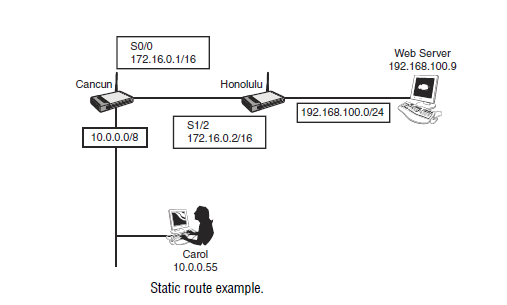
next-hop-address | interface] [distance]For example, in Figure 10.1, Carol is trying to get to a web server on a different
network. Her computer will be configured to use the Cancun router as its
default gateway, but the Cancun router needs to know how to get to the
192.168.100.0/24 network where the web server resides.
Using the Honolulu router as your next hop in the path to the web server, type
the following to create a static route on the Cancun router:
ip route 192.168.100.0 255.255.255.0 172.16.0.2
Instead of routing to the next-hop router, you could also create a static route out of
an interface. If you did not know the address of the Honolulu router, you could tell
the Cancun router to use interface serial 0/0 to get to the 192.168.100.0 network.
The syntax would then be
ip route 192.168.100.0 255.255.255.0 serial 0/0.
At this point, you have created a route to get to the 192.168.100.0 network
attached to the Honolulu router. That will get Carol’s data to the web server, but
the Honolulu router will also need a route to get traffic back to Carol’s network.
Using the Cancun router as the next hop, the syntax would be
ip route 10.0.0.0 255.0.0.0 172.16.0.1
Remember that when entering the static route, the destination is a network
address, whereas the next-hop address is a specific IP address assigned to another
router’s interface. As noted previously, you can also create a static route to
direct your traffic through a specific interface.
Default Routes
A default route is similar to a static route, but instead of configuring a route to
a specific network, you are configuring the router to know where to send traffic
for any network not found in its routing table. Default routes are used to establish
a gateway of last resort for your router.
There are two ways to create a default route. The first is to use the same command
that you used for a static route but use the 0.0.0.0 network as your destination
with a subnet mask of 0.0.0.0. For example, to establish a default route to
send traffic out serial 0/0 destined for any network not learned through dynamic
or static means, type the following:
ip route 0.0.0.0 0.0.0.0 serial 0/0
If you chose to specify the next-hop IP address of the router, you could type the
following instead (assuming a next-hop address of 192.168.1.1):
ip route 0.0.0.0 0.0.0.0 192.168.1.1
Cancun Honolulu
Web Server
192.168.100.9
S0/0
172.16.0.1/16
S1/2
172.16.0.2/16
192.168.100.0/24
10.0.0.0/8
Carol
10.0.0.55
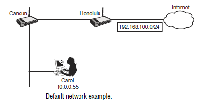
The second method of creating a default route is to use the
ip default-networkcommand. With this command, any traffic destined for networks not found in
the routing table will be sent to the default network. Figure 10.2 illustrates the
use of the default network. If Carol is trying to access the Internet, a default
route could be configured with the following global configuration command on
the Honolulu router:
Honolulu(config)#
ip default-network 192.168.100.0Note that you do not include the subnet mask in this command. Routing protocols,
such as RIP, can propagate this default network to other routers. When
Carol attempts to access the Internet, her computer sends traffic to the Cancun
router, which is her default gateway. The Cancun router will see a default network
of 192.168.100.0, look up this destination in its routing table, and forward
her packets to the Honolulu router. The Honolulu router, in turn, will forward
the traffic out its interface connected to the 192.168.100.0 network and onto the
Internet.
Dynamic Routes
Static and default routes are nice, but they are not scalable. If you need a scalable
solution, you need to experiment with dynamic routing protocols. For the
ICND1 exam, you need to know how to configure RIP, static, and default routing.
Before we get into the details of each of these routing methods, you should first
understand some of the characteristics of all routing protocols. These characteristics
include administrative distances, metrics, distance vector, and link state operations.
Administrative Distance
Administrative distance
is the measure of trustworthiness that a router assigns to howa route to a network was learned. A route can be learned if the network is directly
connected, there is a static route to the network, or by various routing protocols as
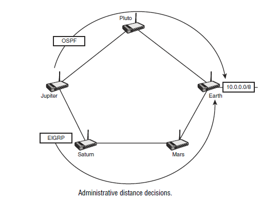
they exchange information about networks between routers. For example, in Figure
10.3, the Jupiter router needs to determine the best route to get to the 10.0.0.0/8
network attached to the Earth router. It has learned of two separate paths; one is
learned through EIGRP and the other through OSPF. EIGRP has decided that the
best path for a packet destined to the 10.0.0.0/8 network is through Saturn, Mars,
and finally Earth. On the other hand, OSPF has determined that the best path is
through Pluto and then Earth. The Jupiter router needs to decide which routing
protocol it should trust, or prefer, over the other. The one preferred will be the one
the router listens to when making decisions on how to route.
To determine which routing source is preferred, Cisco has assigned administrative
distances to sources of routing information. A router will choose the route
that is learned through the source with the lowest administrative distance. Next table
shows the default administrative distance value.
It is possible to change the administrative distance of a static route by appending a
different administrative distance to the end of the command. For example, the following
command assigns the administrative distance of 130 to a static route:
ip route 10.0.0.0 255.0.0.0 serial 0/0 130
Changing the administrative distance of a static route is commonly used when configuring
a backup route, called a floating static route. If you do not specify an administrative
distance at the end of the static route, the default is being used. For the exam,
you should be able to look at the syntax of a static route and know what administrative
distance is being used.
Administrative Distances
Connected 0
Static 1
EIGRP (internal) 90
OSPF 110
RIP (version 1 and 2) 120
EIGRP (external) 170
Make sure that you memorize this table. You should know both the values and understand
the concept of administrative distances. Remember, the lowest number is preferred.
It might help you to memorize these by remembering the word “Eeyore”—
E-OR, for EIGRP, OSPF, and RIP. This is the order of the dynamic routing protocols.
(EIGRP external routes are discussed in Chapter 14, “Routing.”) They are also alphabetical
The Jupiter router would take the EIGRP learned path through
Saturn and Mars to get to the 10.0.0.0/8 network attached to the Earth router.
EIGRP has a lower administrative distance (90) than OSPF (110) and is therefore
preferred.
Metrics
In the previous example, two routing protocols run on the routers, but OSPF
and EIGRP chose two different paths to get to the Earth router. Each routing
protocol has its own algorithm to determine what it considers to be the best path
to a destination network. The main factor in deciding the best path is the routing
protocol’s
metric.Introduction
205
A metric is the variable used in the algorithm when making routing decisions.
Each routing protocol uses a different type of metric. Table 10.2 illustrates the
different metrics used by routing protocols.
Routing MetricsRouting Protocol Metric Description
RIP Hop Count The number of hops, or routers, that a packet
has to pass through to reach a destination. The
route with the lowest hop count is preferred.
EIGRP Bandwidth, Delay Uses Bandwidth and Delay by default, but also
can factor Reliability, Load, and Maximum
Transmission Unit (MTU).
OSPF Cost Cost is defined as 108/bandwidth.
Metrics are not the only thing that distinguishes the routing protocols. Routing
protocols can be further classified into two categories:
.
Distance vector routing protocols.
Link state routing protocolsDistance Vector Routing Protocols
Distance vector routing protocols include RIP and the now unsupported legacy
protocol, Interior Gateway Routing Protocol (IGRP). EIGRP is a hybrid that
contains many of the characteristics of a distance vector protocol. Characteristics
of distance vector routing protocols are as follows:
.
Periodically broadcasts entire routing table out of all interfaces..
Trusts what the other router tells it. (For this reason, distance vectorrouting is sometimes called “routing by rumor.”)
Controlling Routing Loops
Because distance vector routing protocols trust the next router without compiling
a topology map of all networks and routers, distance vector protocols run the
risk of creating loops in a network.
This is analogous of driving to a location without a map. Instead, you trust what
each sign tells you. Trusting the street signs might get you where you want to go,
but I’ve been in some cities where trusting what the signs say will lead you in loops.
The same is true with distance vector routing protocols. Simply trusting what the
next router tells it can potentially lead the packets to loop endlessly. These loops
could saturate a network and cause systems to crash. This, in turn, makes managers
very upset and means that you have to work late into the evening to fix it.
Luckily, distance vector protocols have some mechanisms built in to them to
prevent loops. These mechanisms are as follows:
.
Maximum hop count.
Split horizon.
Route poisoning.
Poison reverse.
Holddown timers.
Triggered updatesRouters maintain a routing table which is stored in RAM. The routing table
lists every network the router has learned about and the number of hops, or
routers, it takes to go through to get to a destination network. For example, if a
packet sent from a router needs to go through two other routers to get to the
destination network, a hop count of two would be recorded. All distance vector
routing protocols maintain a record of hop count even if they do not use hop
count in their routing decisions.
Examine Figure 10.4. Through the use of a dynamic routing protocol, each
router will exchange information with the next router. Mars will learn of the
networks known by Saturn and Jupiter, and Mars will let Saturn and Jupiter
know of the networks that Mars knows about. The next table shows the networks
and associated hop counts for each router.
BLE 10.3 Hop Count
Network 10.0.0.0 Network 11.0.0.0 Network 12.0.0.0 Network 13.0.0.0Jupiter 0 0 1 2
Mars 1 0 0 1
Saturn 2 1 0 0
Distance vector routing protocols keep track of hop counts because if a route
exceeds a maximum hop count limit (determined differently by each routing
protocol), the network is considered unreachable. This prevents packets from
cycling endlessly across your networks. Table 10.4 shows the maximum hop
count for distance vector protocols.
Maximum Hop Count Values
Routing Protocol Maximum Hop Count
RIP 15
EIGRP 224
EXAM ALERT
Make sure that you know the maximum hop count for all routing protocols. Note that
OSPF is not mentioned here. OSPF is a link-state protocol and has an unlimited hop
count.
Having a maximum hop count should be enough to prevent loops, but because
loops are so dangerous, other methods are used as well. The second method to
prevent routing loops is split horizon. The split horizon rule states that information
about a route should not be sent back in the direction in which it was learned.
Look back at Figure 10.4. The split horizon rule states that if Saturn tells Mars
about the 13.0.0.0/8 network, Mars should not advertise it back to Saturn. If it
did, Saturn would be confused and think that it could possibly use Mars to get
to the 13.0.0.0 should its interface to that network ever go down. This would
cause a packet to loop endlessly as the packet would go to Mars, which would in
turn send it back to Saturn. Split horizon resolves this issue by ensuring that the
Mars router never sends information about the 13.0.0.0 network back to the
Saturn router that it heard it from.
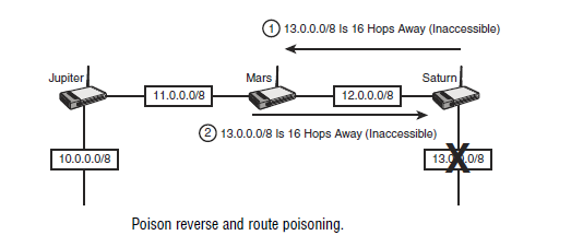
To make absolutely sure that no loops are created, route poisoning and poison
reverse are also implemented. With route poisoning, as soon as a network is
thought to be down, it is advertised out with a hop count that is one greater than
what is allowed. This would declare the route as being inaccessible. Poison
reverse does the same thing but in reverse. The router that hears about a down
network, violates split horizon, and sends back an update with the network being
unreachable. Figure 10.5 illustrates how this would look if the routers were running
RIP, where the maximum hop count is 15 and a hop count of 16 declares
the route inaccessible.
The next mechanism to prevent loops is holddown timers. When a router
receives information that a network is possibly down from a neighbor router, it
will not accept any new information from that router for a specified period of
time. This is to prevent regular update messages from reinstating a down route.
The default holddown timer for RIP is 180 seconds.
Finally, triggered updates are used to prevent loops by exchanging routing information
whenever there is a change. In other words, a change in the routing
topology will trigger routers to update each other. Without triggered update, a
router would have to wait for the next update interval to learn of a changed route.
During that period when a route is changed and when the next routine update is
sent out there is a potential of a loop. To lessen the risk of a loop during this waiting
period, routers will not wait for the update interval to send out the information
about a changed network but will instead send out the information
immediately. This way all routers can learn of the change as soon as possible.
Link State Routing Protocols
If distance vector routing protocols are like trusting the highway signs when you
are on a road trip, link state routing protocols are like having the map in front
of you. With link state routing protocols such as OSPF, your router will know
all the networks and the various paths to the networks.
The Cisco Hybrid: EIGRP
Extra! Extra! Read all about it! EIGRP solves the world’s problems. It’s the best
of both worlds! You get the best of link state and distance vector routing all built
in to one protocol!
Okay, so perhaps that’s a little more hype than necessary, but it is not that far
from the truth. EIGRP is a Cisco-proprietary protocol that combines characteristics
of link state and distance vector routing protocols. For example, like a link
state routing protocol, it sends out hello messages to discover its neighbors.
However, it does not have a built-in hierarchical design like OSPF, thus making
it more like a distance vector. The operations and configurations of EIGRP and
OSPF are not tested on in the ICND1 exam, but you will want to know the differences
between link state and distance vector protocols. You read more about
EIGRP later, but for now let’s start with a very simple protocol, RIP.
EXAM ALERT
Know the characteristics of distance vector and link state routing protocols and know
which of these categories each routing p
rotocol falls into.RIP
The Routing Information Protocol (RIP) uses the Bellman-Ford algorithm,
which simply counts the number of hops, or routers, to a destination network
and chooses the path that is the fewest number of hops. Any destination that is
more than 15 hops away is considered inaccessible.
Characteristics of RIP
RIP routers exchange information by broadcasting the entire routing table every
30 seconds out all interfaces with RIP enabled. RIP version 2 also sends out
updates every 30 seconds but sends out updates using the multicast address of
224.0.0.9 (can be configured to do unicast as well). In addition, version 2 provides
the following benefits not available in version 1:
.
Routing authentication.
Classless routing.
SummarizationImplementing RIP
Configuring RIP is straightforward. The four steps to configuring a routing
protocol are as follows:
1.
Enable the routing protocol.2.
Activate it on interfaces.3.
Advertise directly on networks.4.
Configure optional parameters.The first step, enable the routing protocol, is done from global configuration
mode by typing
router rip. The next two steps, activating RIP on interfaces andadvertising networks, is done with a single command, the
network command.If you look at the next figure you will see three routers named Larry, Curly, and Moe.
For the Moe router, you need to enable RIP and enter the networks you want
to advertise. The Moe router has the 192.168.10.0/24 and 192.168.20.0/24 networks
directly connected to it. Moe’s configuration would be
Moe(config)#
router ripMoe(config-router)#
network 192.168.10.0Moe(config-router)#
network 192.168.20.0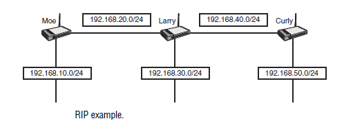
Larry has three networks attached to his router. His configuration would be
Larry(config)#
router ripLarry(config-router)#
network 192.168.20.0Larry(config-router)#
network 192.168.30.0Larry(config-router)#
network 192.168.40.0Finally, we can’t forget Curly. Curly’s configuration would be
Curly(config)#
router ripCurly(config-router)#
network 192.168.40.0Curly(config-router)#
network 192.168.50.0When you enter your networks in your RIP configuration, RIP is activated on
the interfaces that are assigned those networks. All networks that you listed in
your configuration are then sent out all RIP-activated interfaces. Thus, the networks
that you entered on Curly’s router will be sent out to Larry. Larry will
take what he learned from Curly, add his own networks, and send them out to
Moe. Larry will also learn networks from Moe, add his own networks, and send
them out to Curly.
Remember to enter only your directly connected networks. Curly, for example,
should not enter 192.168.10.0/24 in his configuration because that network is
not directly connected to his router. Also, you should enter classful networks
only. A classful network is the major class A, B, or C network with the default
masks of /8, /16, or /24. This means that even if you are subnetting, you should
enter the major Class A, B, or C address. In Figure 10.7, our three friends have
new networks that are taken from a major Class A network. Even though multiple
networks are attached to them, enter only the major 10.0.0.0/8 network.
Thus, all three routers would have the same configuration:
Router(config)#
router ripRouter(config-router)#
network 10.0.0.0Finally, you may enter some optional commands. The two optional commands
that you should be familiar with for the exam are as follows:
.
version 2.
no auto-summaryBoth commands are entered under the RIP routing process. The first command,
version 2
, enables RIP version 2 on your router. RIP version 2 adds the benefitsof optional authentication, multicast updates, summarization, and classless
routing. Although RIP version 2 does support classless routing, it still automatically
summarizes all networks on the default Class A, B, and C boundaries. In
our previous example in Figure 10.7, RIP version 2 still summarizes the networks
at the major 10.0.0.0/8 boundary. (/8 is the default mask for a Class A
network.) To disable automatic summarization, enter the no auto-summary command
under the routing process. Using Figure 10.7 again, the complete configuration
for Larry’s router, assuming that you wanted RIP version 2 with no
automatic summarization, is
Larry(config)#
router ripLarry(config-router)#
network 10.0.0.0Larry(config-router)#
version 2Larry(config-router)#
no auto-summaryNote that even though we disabled automatic summarization, we still put the
default classful networks in our configuration. RIP is smart enough to go on the
interfaces and discover the individual subnetworks and their associated subnet
masks.
EXAM ALERT
The three classless routing protocols in this chapter are RIPv2, EIGRP, and OSPF.
Remember these three protocols. Also, classless routing, VLSM, summarization,
supernetting (another term for summarization), and route aggregation are all related,
so if you are asked which routing protocols support these, remember RIPv2, EIGRP,
and OSPF.
Verifying and Troubleshooting RIP
Now that RIP is configured, you should verify your configuration. There are
two commands that you can use to verify proper operation of RIP:
.
show ip route.
show ip protocolsThe first command displays your routing table. For the sake of simplicity, we’ll
go back to our original example of our three friends before they got creative and
started subnetting. Figure 10.8 shows the Larry, Curly, and Moe routers before
they subnetted. This time, the names of the interfaces have been included.
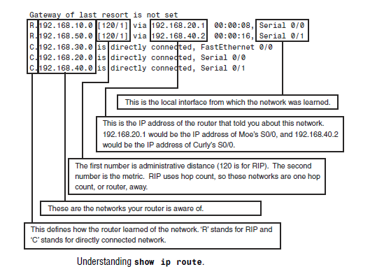
After executing the show ip route command on Larry’s router, you should see
the following:
Gateway of last resort is not set.
R 192.168.10.0 [120/1] via 192.168.20.1 00:00:08, Serial 0/0
R 192.168.50.0 [120/1] via 192.168.40.2 00:00:16, Serial 0/1
C 192.168.30.0 is directly connected, FastEthernet 0/0
C 192.168.20.0 is directly connected, Serial 0/0
C 192.168.40.0 is directly connected, Serial 0/1
in order
On Moe’s router, the output looks as follows:
Gateway of last resort is not set.
R 192.168.30.0 [120/1] via 192.168.20.2 00:00:20, Serial 0/0
R 192.168.40.0 [120/1] via 192.168.20.2 00:00:20, Serial 0/0
R 192.168.50.0 [120/2] via 192.168.20.2 00:00:20, Serial 0/0
C 192.168.10.0 is directly connected, FastEthernet 0/0
C 192.168.20.0 is directly connected, Serial 0/0
Notice how the hop count for the 192.168.50.0 network is 2 because that network
is two hops away. You must go through the Larry and Curly router to get
to this network.
Curly’s router has the following output:
Gateway of last resort is not set.
R 192.168.10.0 [120/2] via 192.168.40.1 00:00:4, Serial 0/0
R 192.168.20.0 [120/1] via 192.168.40.1 00:00:4, Serial 0/0
R 192.168.30.0 [120/1] via 192.168.40.1 00:00:4, Serial 0/0
C 192.168.50.0 is directly connected, FastEthernet 0/0
C 192.168.40.0 is directly connected, Serial 0/0
The second RIP command you should use is the show ip protocols command
to verify the operation of RIP on your router. Among other things, this command
shows you the timers and the networks you are routing. These networks
are the same ones you entered under the RIP routing process. Following is the
output of this command on the Larry router:
Larry#
show ip protocolsRouting Protocol is “rip”
Sending updates every 30 seconds, next due in 19 seconds
Invalid after 180 seconds, hold down 180, flushed after 240
Outgoing update filter list for all interfaces is
Incoming update filter list for all interfaces is
Redistribution: rip
Default version control: send version 1, receive any version
Interface Send Recv Triggered RIP Key-chain
FastEthernet0/0 1 1 2
Serial0/0 1 1 2
Serial0/1 1 1 2
Routing for Networks:
192.168.20.0
192.168.30.0
192.168.40.0
Routing Information Sources:
Gateway Distance Last Update
192.168.20.1 120 00:00:02
192.168.40.2 120 00:00:26
Sometimes things do not work the way you anticipated. If this happens, you may
want to turn on debugging. Use the debug ip rip command to debug the routing
process.
CAUTION
You should be very careful when using debug commands. If there is a significant amount
of output being generated, it can crash your router. Only turn on debugging if you know it
is safe in your environment. If you are not sure, contact Cisco’s Technical Assistance
Center (TAC) before debugging.
Executing this command on Moe’s router generates the following output:
Moe#
debug ip rip1. RIP: received v1 update from 192.168.20.2 on Serial0/0
2. 192.168.30.0 in 1 hops
3. 192.168.40.0 in 1 hops
4. 192.168.50.0 in 2 hops
5. RIP: sending v1 update to 255.255.255.255 via Serial0/0
(192.168.20.1)
6. network 192.168.10.0, metric 1
7. RIP: sending v1 update to 255.255.255.255 via FastEthernet0/0
(192.168.10.0)
8. network 192.168.20.0, metric 1
9. network 192.168.30.0, metric 2
10. network 192.168.40.0, metric 2
11. network 192.168.50.0, metric 3
For sake of clarity, each line of this output has been numbered.
The metric is added as it leaves the router. By looking at the networks being sent
out with a metric of 1, we can glean that this router is configured to route for
networks 192.168.20.0 and 192.168.10.0 (lines 6 and 8). You can also look at the
interface IP addresses to see what networks are directly connected to the router
(lines 5 and 7).
From this output, you can also tell that split horizon works. The split horizon
rule states that you never advertise a route out of the interface through which it
was learned. This router has learned three networks on interface serial 0/0 (lines
2, 3, and 4), but has not advertised out of any of them (line 6).
You need to feel comfortable reading the output of the debug IP RIP command.
Remember, it is not useful to send information back in the direction from which it
came or to the source from which it came. If the learned route is not returned through
the same interface on which it was received, the split horizon rule is in effect.