Bridging and Switching
Bridges and switches are devices that segment (break up) collision domains.
They are important parts of a network infrastructure, and the concepts presented
here are heavily tested on the CCNA exam(s).
Functions of Bridges and Switches
When talking about LANs at the CCNA level, we are almost exclusively interested
in ethernet.
In the early implementations of Ethernet, every device connected to a single wire.
Thicknet (10-BASE 5) and Thinnet (10-BASE 2) were the most common physical
layer implementations. A little later, hubs were used. All these technologies did
effectively the same thing: connect many hosts together so that one of them at a
time could transmit on the wire. This created a single, often large, collision
domain. As you recall , the bigger the collision domain, the more
collisions and the less data that actually gets sent. In these types of implementations,
you can lose 50–60% of the available bandwidth just because of collisions. So
if we had a 10-BASE T hub, not only did we actually end up with only about 4 or
5Mbs instead of 10Mbs, but that reduced bandwidth must also be shared by all the
devices on that segment, instead of each device getting the full 10Mbs. Breaking up
(segmenting) collision domains is necessary to make them small enough so that
devices can reliably transmit data. We can segment using routers, but routers are
expensive and difficult to configure; in addition, they don’t typically have very many
ports on them, so we would need a lot of them to segment effectively.
Bridges were developed to address this issue. A
bridge isolates one collisiondomain from another while still connecting them and selectively allowing
frames to pass from one to the other. A
switch is simply a bigger, faster bridge.Every port on a switch or bridge is its own collision domain. The terms bridge
and switch can be used interchangeably when discussing their basic operations;
we use the term
switch because switches are more modern and more common.A switch must do three things:
.
Address learning.
Frame forwarding.
Layer 2 loop removalAddress Learning
Address learning
refers to the intelligent capability of switches to dynamicallylearn the source MAC addresses of devices that are connected to its various
ports. These addresses are stored in RAM in a table that lists the address and the
port on which a frame was last received from that address. This enables a switch
to selectively forward the frame out the appropriate port(s), based on the destination
MAC address of the frame.
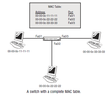
Anytime a device that is connected to a switch sends a frame through the switch,
the switch records the source MAC address of the frame in a table and associates
that address with the port the frame arrived on. In the next figure it illustrates a
switch that has learned the MAC addresses of the three hosts connected to it, as
well as the ports to which they are connected.
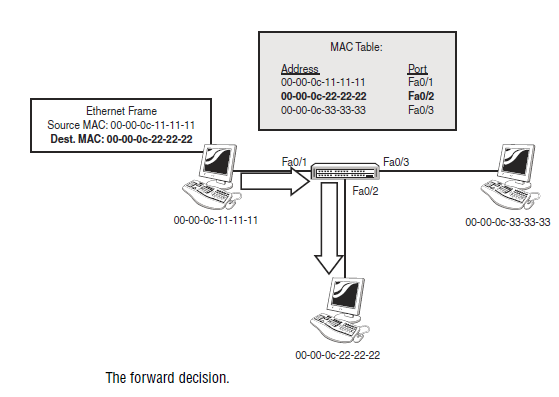
Frame Forwarding
After a switch has learned the MAC addresses of the devices connected to it, it
can intelligently forward unicast frames to the correct host by comparing the
destination MAC of the frame with the addresses in its MAC table; when it finds
a match, it then sends the frame out the port associated with that entry. In the next figure
the forwarding decision made by the switch.
This is where switches create such a benefit to an Ethernet network: If a switch
knows the port to which the destination MAC is connected, the switch will send
the frame out that port and only that port. This prevents the traffic from being
unnecessarily sent to hosts that it is not intended for, significantly improving the
efficiency of the network. This is in sharp contrast to the behavior of a hub,
which always sends all frames out all ports except the one it came in on (to avoid
a false collision detection by the sending station).
There are some situations in which a switch cannot make its forwarding decision,
however. Consider the case in which one of the hosts sends out a broadcast.
The MAC address for a broadcast is FF-FF-FF-FF-FF-FF; this is
effectively the MAC address of all hosts because every host in a broadcast
domain must receive all broadcasts. When the switch receives a broadcast frame
inbound on one of its ports, it will check that the source MAC is correctly listed
in its MAC table (and update it if necessary) and check the destination MAC
of the frame for a match in the table. Because FF-FF-FF-FF-FF-FF matches the
MAC of all hosts, the switch must
flood the frame—it sends it out every port(except the one it came in on) so that the broadcast frame will reach all possible
hosts. At this point, the switch is behaving like a hub. This also illustrates why
switches (by default) do not segment broadcast domains.
Another scenario in which a switch (by default) is unable to be optimally efficient
in the delivery of frames is in the case of a multicast. A
multicast is a messagesent by one host and intended for a specific group of other hosts. This
group could be a single host or a very large number of hosts in different places.
The key here is that a single host transmits a stream of data (perhaps a video of
a speech or event) to a group of hosts. By default, the switch will treat this the
same way as a broadcast, flooding it out all ports to make sure that it reaches all
the possible hosts in the group. This is inefficient because the traffic also hits
those hosts who do not want the stream. There are several mechanisms and configurations
to set it so that only the hosts in the multicast group receive the multicast,
but that is well out of the scope of the CCNA exam; the CCNP Building
Cisco Multilayer Switched Networks course covers this topic.
The switch will also flood a frame if it does not have an entry in its MAC table
for the destination MAC in the frame. Although this happens rarely, if the
switch doesn’t know which specific port to send the frame out, it responds by
doing the safest thing and flooding that frame so that it has the best chance of
reaching the correct destination. Interestingly, after the destination host
responds to that first frame, the switch will enter the missing MAC address into
its table and the flood probably won’t happen again.
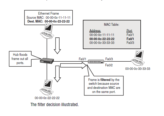
The last situation we should examine is what happens if the sending and receiving
hosts are both connected to the same port on the switch. This is most commonly
seen when the two hosts are connected to a hub, which is in turn
connected to a switch. From the switch’s perspective, the two hosts are on the
same port. When the sending host transmits a frame, the hub does its thing and
floods it out all ports, including the ones connected to the intended receiver and
the switch. The receiver simply receives it; the switch checks the source MAC
of the frame, updates its MAC table if necessary, and then checks the destination
MAC in its table to see which port it should be sent out. When it discovers that
the two MACs are associated with the same port, it
filters the frame: The switchdoes not transmit the frame out any ports and assumes that the frame will reach
its intended recipient without help from the switch.
You should understand how a switch responds
To unicast, broadcast, and multicastframes, and you must know the filter, forward, and flood decision processes. You
should also have a clear understanding of the advantages of switches over hubs.
You have seen how switching gives you a huge efficiency advantage over hubs
and coaxial media. Even a low-end switch is preferable to any kind of hub or
coax media. You want to be sure that you get the right equipment for the job;
different switches run at various speeds, and have diverse limitations on the
number of MAC addresses they can support. Although almost any switch is better
than any hub, you should take stock of your network, how many hosts, how
much and what kind of traffic you expect to support, and then choose the switch
that best meets your performance and budget requirements.
The Differences Between Switches and Bridges
We have been using the term “switch” interchangeably with “bridge,” but there
are some significant differences that you need to know about. The key difference
is in the technology. Bridges, which are older, do all the work of frame
analysis and decision making in software, using the CPU to analyze data stored
in RAM. Switches use ASIC (Application-Specific Integrated Circuit) chips.
ASICs are specialized processors designed to do one thing—in this case, switch
frames. Depending on the model of switch, the speed difference can be astounding:
A bridge typically switches around 50,000 frames per second, whereas a
lowly 2950 switch can move an average of 12 million frames per second. (This,
of course, depends on the frame size.) A big switch, such as the Catalyst 6500
series, could do 10 times that, depending on the hardware configuration.
Switches also tend to have many more ports than bridges; a bridge by definition
has at least 2 ports, and they didn’t get much bigger than 16 ports. Switches can
have hundreds of ports if you buy the appropriate expansion modules.
Other differences include the following:
.
Switches support half and full duplex, bridges only half duplex..
Switches support different port speeds (10 and 100Mbs, for example),but a bridge’s ports must all be the same speed.
.
Switches support multiple VLANs and an instance of Spanning Tree forevery VLAN (more on this soon).
Switches and Bridges ComparedComparison Switches Bridges
Switching Technology ASIC (Hardware) Software
Speed Fast Slow
Port Density High Low
Duplex Full and Half Half Only
VLAN-Aware Yes No
Collision Domains 1 per Port 1 per Port
Broadcast Domains 1 per VLAN 1
STP Instances 1 per VLAN 1
EXAM ALERT
Know the differences between switches and bridges.
Switching Modes
Switches examine the source and destination MAC in a frame to build their
MAC table and make their forwarding decision. Exactly how they do that is the
topic of this section. You need to be aware of three switching modes: Store and
Forward, Cut Through, and Fragment Free.
Store and Forward
Store and Forward is the basic mode that bridges and switches use. It is the only
mode that bridges can use, but many switches can use one or more of the other
modes as well, depending on the model. In Store and Forward switching, the
entire frame is buffered (copied into memory) and the Cyclic Redundancy
Check (CRC), also known as the FCS or Frame Check Sequence is run to
ensure that the frame is valid and not corrupted.
NOTE
A CRC is a simple mathematical calculation. A sample of the data (in this case, a frame) is
used as the variable in an equation. The product of the equation is included as the CRC at
the end of the frame as it is transmitted by the source host. When it is received by the
switch, the same equation is run against the same sample of data; if the product value is
the same as the value of the CRC in the frame, the frame is assumed to be good. If the
value is different, the frame is assumed to be corrupt or damaged, and the frame is
dropped. This analysis happens before the forwarding decision is made.
Cut Through
Cut Through is the fastest switching mode. The switch analyzes the first six
bytes after the preamble of the frame to make its forwarding decision. Those six
bytes are the destination MAC address, which, if you think about it, is the minimum
amount of information a switch has to look at to switch efficiently. After
the forwarding decision has been made, the switch can begin to send the frame
out the appropriate port(s), even if the rest of the frame is still arriving at the
inbound port. The chief advantage of Cut Through switching is speed; no time
is spent running the CRC, and the frame is forwarded as fast as possible. The
disadvantage is clearly that bad frames will be switched along with the good.
Because the CRC/FCS is not being checked, we might be propagating bad
frames. This would be a bad thing in a busy network, so some vendors support
a mechanism in which the CRCs are still checked but no action is taken until the
count of bad CRCs reaches a threshold that causes the switch to change to Store
and Forward mode.
Fragment Free
Fragment Free mode is a switching method that picks a compromise between
the reliability of Store and Forward and the speed of Cut Through. The theory
here is that frames that are damaged (usually by collisions) are often shorter than
the minimum valid ethernet frame size of 64 bytes. Fragment Free buffers the
first 64 bytes of each frame, updates the source MAC and port if necessary, reads
the destination MAC, and forwards the frame. If the frame is less than 64 bytes,
it is discarded. Frames that are smaller than 64 bytes are called
runts; FragmentFree switching is sometimes called “runtless” switching for this reason. Because
the switch only ever buffers 64 bytes of each frame, Fragment Free is a faster
mode than Store and Forward, but there still exists a risk of forwarding bad
frames, so the previously described mechanisms to change to Store and Forward
if excessive bad CRCs are received are often implemented as well.
EXAM ALERT
Know the three switching modes and how they work.
Switch Connections
Switches have the capability of connecting to various types of devices: PCs,
servers, routers, hubs, other switches, and so on. Historically, their role was to
break up collision domains, which meant plugging hubs into them. This meant
that the switch port had to be able to connect in the same way as the hub—using
CSMA/CD, which in turn implies half duplex.
Half duplex means that only one device can use the wire at a time; much like a
walkie-talkie set, if one person is transmitting, the other(s) must listen. If others
try to transmit at the same time, all you get is a squawk, which is called a collision
in network terms. Hubs can use only half-duplex communication. Some
older NICs (network interface cards), whether for PCs or even for older routers
such as the Cisco 2500 series, can use only half duplex as well.
Full duplex is more advanced. In this technology, a device can send and receive
at the same time because the send wire is connected directly to the receive wire
on both connected devices. This means that we get the full bandwidth of the link
(whether 10Mbs, 100Mbs, or 1Gbs) for both transmit and receive, at the same
time, for every connected device. If we have a 100Mbs FastEthernet connection
using full duplex, it can be said that the total available bandwidth is 200Mbs.
This doesn’t mean 200Mbs up or 200Mbs down, but is the sum of the full
100Mbs up and 100Mbs down for that link; some sales documentation might
gloss over this point in an effort to make the switch look better on paper.
Full duplex does give us a major boost in efficiency because it allows for a zero collision
environment: If every device connected to a switch can send and
receive at the same time, they cannot collide with each other. The only possible
conflict (collision is not the right term here) is within the switch itself, and this
problem (should it even happen) is handled by the switch’s capability to buffer
the frames until the conflict is cleared. Setting up a switch so that every device
connected to it is running full duplex (and therefore there are no collisions) is
sometimes called
microsegmentation because every device has been segmentedinto its own collision domain, in which there are no collisions. You might see a
reference to the collision detection circuit being disabled on a switch as soon as
full duplex is selected for a switch port. Note that full-duplex connections can
be only point-to-point, meaning one full-duplex device connected to one switch
port; half-duplex connections are considered multipoint, which makes sense
when you consider that a hub might be connected to a switch port, and there
might be several hosts connected to the hub.
Note that not every NIC, whether on a PC or a router, can support full duplex,
although it is very rare these days to find a NIC that does not. Most newer NICs
have the capability of full duplex, and virtually all switches do as well; furthermore,
most NICs and some switches can perform an autosensing function to
determine whether the link is full duplex and set themselves accordingly.
TIP
It is a good practice to set the duplex of certain connections manually to full duplex (or
half where necessary), instead of using the Auto function. Connections to other switches,
routers, or important servers should be stable and well known enough to set as full
duplex. Doing so avoids potential problems in which the duplex negotiation fails, causing
a degradation or loss of connectivity. For connections to hosts, where we don’t necessarily
have control over the NIC settings, the Auto function is useful.
Duplex Configuration
Setting the appropriate duplex mode is done at the interface configuration
prompt. The choices you have are Auto, Full, or Half; the default is Auto, so
your switch should work in most cases if you do not make any configuration
changes at all. Note that if you manually set duplex to Half or Full, the interface(
s) will be locked to that setting and will no longer use the Auto negotiation
to dynamically determine the duplex setting of the link(s).
Following is an example of a configuration that sets Interface FastEthernet 0/1
to Full duplex/100Mbs, Interface 0/2 to Half Duplex/10Mbs, and Interface 0/3
Auto Duplex/Auto speed:
2950#
config terminal2950(config)#
interface fastethernet 0/12950(config-if)#
duplex full2950(config-if)#
speed 1002950(config-if)#
interface fastethernet 0/22950(config-if)#
duplex half2950(config-if)#
speed 102950(config-if)#
interface fastethernet 0/32950(config-if)#
duplex auto2950(config-if)#
speed autoSTP
Earlier, we mentioned that one of the functions of a switch was Layer 2 Loop
removal. The Spanning Tree Protocol (STP) carries out this function. STP is a
critical feature; without it many switched networks would completely cease to
function. Either accidentally or deliberately in the process of creating a redundant
network, the problem arises when we create a looped switched path. A
loopcan be defined as two or more switches that are interconnected by two or more
physical links.
Switching loops create three major problems:
.
Broadcast storms—Switches must flood broadcasts, so a looped topologywill create multiple copies of a single broadcast and perpetually cycle
them through the loop.
.
MAC table instability—Loops make it appear that a single MACaddress is reachable on multiple ports of a switch, and the switch is constantly
updating the MAC table.
.
Duplicate frames—Because there are multiple paths to a single MAC, itis possible that a frame could be duplicated in order to be flooded out all
paths to a single destination MAC.
All these problems are serious and will bring a network to an effective standstill
unless prevented.
The next figure illustrates a looped configuration and some of the problems it can
create.
%20loop.png)
Other than simple error, the most common reason that loops are created is because
we want to build a redundant or fault-tolerant network. By definition, redundancy
means that we have a backup, separate path for data to follow in the event the first
one fails. The problem is that unless the backup path is physically disabled—
perhaps by unplugging it—the path creates a loop and causes the problems mentioned
previously. We like redundant systems; we do not like loops and the problems
they cause. We need a mechanism that automatically detects and prevents
loops so that we can build the fault-tolerant physical links and have them become
active only when needed. The mechanism is called the
Spanning Tree Protocol; STPis a protocol that runs on bridges and switches to find and block redundant looped
paths during normal operation. Spanning Tree was originally developed by the
Digital Equipment Corporation (DEC), and the idea was adopted and modified by
the IEEE to become 802.1d. The two are incompatible, but it is exceedingly rare
to find a DEC bridge these days, so the incompatibility is not usually a problem.
Exam Alert
STP eliminates Layer 2 loops in switched networks with redundant paths.