|
|
 |
|
|
In our next
project the user will build a network that utilizes distance vector
(RIP and , hybrid (EIGRP), and link state (OSPF) routing protocols running
in parallel to see how administrative distance, hop count, bandwidth, and
load balancing play roles in what the router chooses as the best route.
Configurations are then verified through show and debug commands. Note:
Omit IGRP, which is no longer
used.
Configuring RIP, EIGRP, and OSPF.

Lab Summary
|
vLab Title |
1137 Configuring RIP, EIGRP, and OSPF |
|
Skills |
Basic IP configuration of multiple routing protocols on a Cisco
router which includes:
Configuring IP RIP routing
Configuring IP IGRP routing
Configuring IP EIGRP routing
Configuring OSPF routing
Migrating from RIP to IGRP
Migrating from IGRP to EIGRP
Migrating from EIGRP to OSPF
Verifying administrative distance
Reviewing IP RIP debug information
Reviewing IP IGRP transactions debug information
Reviewing IP EIGRP debug information
Reviewing OSPF adjacency debug information
Interpreting the routing table
Verifying network connectivity using ping |
|
Level Of Difficulty |
Basic |
|
Course |
ICND |
|
Lab Length |
240 minutes |
|
Certification |
CCNA |
|
Desired Learner Outcome |
The user will build a network that utilizes distance vector
(RIP and, hybrid (EIGRP), and link state (OSPF) routing
protocols running in parallel to see how administrative
distance, hop count, bandwidth, and load balancing play
roles in what the router chooses as the best route.
Configurations are then verified through show and debug
commands. |
|
Desired Network Outcome |
A functioning three-router network using RIP, IGRP, EIGRP,
and OSPF routing protocols. |
|
Dependencies |
The user is expected to have used the Cisco command line
interface (CLI). |
|
|
|
|
|
|
|
Network Type |
3 Location Routed Network |
|
Technology |
Cisco |
|
References |
ICND 2.0 (Interconnecting Cisco Network Devices) - Module 5
Routing Protocols
by Cisco Systems; Cisco IOS Command Documentation.
Significant Commands Used in Lab :
configure terminal
enable
end
exit
ping ip-address
router igrp autonomous-system
router rip
router eigrp autonomous-system
network network-number
router ospf process-id
network network-number wildcard-mask area-id
show ip protocols
show ip route
debug ip rip
debug ip igrp transactions
debug ip eigrp
debug ip ospf adj
no debug all
undebug all
|
Launching Your Lab
The Status of your Lab is displayed at the top of the left
navigation column.
Click the Start Lab Now button. A progress bar displays while the
lab is being initialized. During this time you can view items under
the Content area of the left navigation bar.
When Initialization is complete the Status changes to In Progress.
The clock starts and a lab diagram displays in the main content
area.
Click on the diagram that appears and your virtual lab experience
will begin.
If your connection isn't working, verify connectivity by clicking
Verify Connection in the Tools section on the left navigation bar.
Assignment
Configure RIP, EIGRP, and OSPF on three routers over a serial
network.
Story
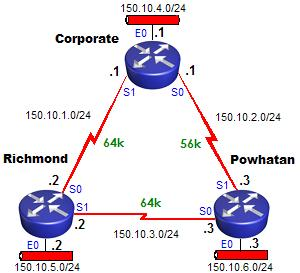
Your network has been configured to match the network diagram above,
however the sites are complaining that there are some network
segments which they can't reach. You have been given a maintenance
window of 90 minutes to get full connectivity among the sites. You
have decided to take advantage of the time to not only fix the
problem, but to also test how running multiple routing protocols in
parallel affect your routing tables.
Start out by testing connectivity from the Corporate router
by pinging all remote interfaces and determine which are
unreachable. For those networks that are unreachable, examine
your routing table on the Corporate router to view known
networks.
|
Enabling and Verifying RIP: |
Configure RIP on all
routers and then check the routing table on Corporate to see the
new networks learned by RIP. Make note of the path(s) to the
150.10.3.0 network. RIP should see two equal cost paths. Verify
that full connectivity has been established by pinging all
remote interfaces. View the underlying exchanges of route
information between RIP routers by issuing a RIP debug. After
a few minutes, disable debugging.
|
Enabling and Verifying IGRP: |
Migrate to IGRP on all
routers without removing RIP. Choose any autonomous system number, but
make sure it is the same for every router. Check the routing
table on Corporate to see how the routing table has changed and
make note of the path to the 150.10.3.0 network. The routing table
should now show only one path. Verify the underlying exchanges of
IGRP routing tables between routers using an IGRP debug.
After a few minutes, disable debuggging.
|
Enabling and Verifying EIGRP: |
Migrate to EIGRP on all
routers using an autonomous system number of your choice, without removing
IGRP. Check the routing table on Corporate to see how
configuring EIGRP has affected it. Compare the administrative
distances of the three routing protocols to see why only EIGRP
routes are listed in the routing table.
EIGRP does not send regular periodic updates, but instead exchanges
messages when a topology change occurs. Enable an EIGRP debug
and then force a triggered EIGRP exchange by shutting down your
Serial 0 interface and then re-enabling it.
|
Enabling and Verifying OSPF: |
Configure all routers to be in a single OSPF area, Area 0. View the routing table on Corporate and you should
find that nothing has changed. Compare the administrative
distances of the four routing protocols to see why OSPF routes
are not found in the routing table. Remove EIGRP.
Check the routing table again to see if OSPF routes are now
visible. Because OSPF, like EIGRP, only sends updates when a change
in the network has occured, enable an OSPF debug and then
create a topology change by shutting down and re-enabling Serial 0.
Verify that there is still full connectivity throughout the network
by pinging all remote interfaces from Corporate.
Conditions
You are not to use static routes to fix any connectivity issues you
may find in the lab.
Notes
|
* To be more effective in troubleshooting this lab, click on the
diagram below which is in Packet Tracer Format.
* For a concise list of the tasks you are to perform in this
lab, ping each device to check for consistency
|
Diagram
By clicking on the Diagram Packet Tracer
will load automatically.
NEW: We now
have a model composed in GNS3
Click this button to load:

Suggested Approach
The Suggested Approach identifies what to do based on the
Scenario.
To find more details on how to do a specific task, access the
Sample Solution.
PRIOR TO ENABLING ANY ROUTING PROTOCOLS
* Test connectivity from the Corporate router by pinging
all remote interfaces and determine which are unreachable.
* Examine the routing table on the Corporate router to view
known networks.
ENABLE AND VERIFY RIP
* Configure RIP on all routers.
* View how the routing table has changed on the Corporate router
and make note of the path to the 150.10.3.0 network.
* Verify that you can now ping all remote interfaces from Corporate.
* Verify the real-time exchange of RIP routes with a debug command.
ENABLE AND VERIFY IGRP
* Migrate to IGRP without removing RIP.
* View how the routing table has changed and make note of the path
to the 150.10.3.0 network.
* Verify the real-time exchange of IGRP routes with a debug command.
ENABLE AND VERIFY EIGRP
* Migrate to EIGRP without removing RIP.
* View how the routing table has changed.
* Compare the administrative distances of the three routing protocols.
* Enable a debug to view EIGRP exchanges and force a topology change.
ENABLE AND VERIFY OSPF
* Configure all routers to be in a single OSPF area, area 0.
* View the routing table and you will find it unchanged.
* Compare the administrative distances of the four routing protocols
to see which is lowest.
* Remove EIGRP.
* View how the routing table has changed.
* Enable a debug to view the formation of OSPF adjacencies and force
a topology change.
* Verify that you can still ping all remote interfaces from Corporate
Sample Solution
|
Task Index |
|
Task 1 |
Test connectivity from the Corporate router by pinging all
remote interfaces and determine which are unreachable. |
|
Task 2 |
Examine the routing table on the Corporate router to view
known networks. |
|
Task 3 |
Configure RIP on all routers. |
|
Task 4 |
View how the routing table has changed on the Corporate
router and make note of the path to the 150.10.3.0 network. |
|
Task 5 |
Verify that you can now ping all remote interfaces from
Corporate. |
|
Task 6 |
Verify the real-time exchange of RIP routes with a debug
command. |
|
Task 7 |
Migrate to IGRP without removing RIP. |
|
Task 8 |
View how the routing table has changed and make note of the
path to the 150.10.3.0 network. |
|
Task 9 |
Verify the real-time exchange of routes with a debug
command. |
|
Task 10 |
Migrate to EIGRP without removing any routes. |
|
Task 11 |
View how the routing table has changed on the Corporate. |
|
Task 12 |
Compare the administrative distances of the three routing
protocols. |
|
Task 13 |
Verify the real-time exchange of EIGRP messages with a debug
command. |
|
Task 14 |
Configure all routers to be in a single OSPF area, Area 0. |
|
Task 15 |
View the routing table and you will find it unchanged. |
|
Task 16 |
Compare the administrative distances of the four routing
protocols to see which is lowest. |
|
Task 17 |
Remove IGRP and and EIGRP. |
|
Task 18 |
View how the routing table has changed. |
|
Task 19 |
Enable a debug to view the OSPF adjacency changes. |
|
Task 20 |
Verify that you can still ping all remote interfaces from
Corporate. |
|
Task 1 |
|
Test connectivity from the Corporate router by pinging all
remote interfaces and determine which are unreachable. |
|
Step 1 : Access the Corporate router and enter privileged
EXEC mode.
Action:
{Click on the Corporate router found on the network
diagram, then
press [ENTER] to access the command line interface.
enable
Result:
Configuring RIP, IGRP, EIGRP, and OSPF - Corporate
Revision: Version 1.0
Date: March 12, 2003
Copyright 1998, 1999, Element K LLC
All rights reserved
User Access Verification
Corporate>enable
Corporate#
Step 2 : From Corporate, determine which remote interfaces
are unreachable.
Action:
Ping each interface on Richmond and Powhatan from the
Corporate router.
Result:
Corporate#ping 150.10.1.2
Type escape sequence to abort.
Sending 5, 100-byte ICMP Echos to 150.10.1.2, timeout is 2 seconds:
!!!!!
Success rate is 100 percent (5/5), round-trip min/avg/max = 28/31/32 ms
Corporate#ping 150.10.5.2
Type escape sequence to abort.
Sending 5, 100-byte ICMP Echos to 150.10.5.2, timeout is 2 seconds:
.....
Success rate is 0 percent (0/5)
Corporate#ping 150.10.3.2
Type escape sequence to abort.
Sending 5, 100-byte ICMP Echos to 150.10.3.2, timeout is 2 seconds:
.....
Success rate is 0 percent (0/5)
Corporate#ping 150.10.2.3
Type escape sequence to abort.
Sending 5, 100-byte ICMP Echos to 150.10.2.3, timeout is 2 seconds:
!!!!!
Success rate is 100 percent (5/5), round-trip min/avg/max = 32/35/36 ms
Corporate#ping 150.10.3.3
Type escape sequence to abort.
Sending 5, 100-byte ICMP Echos to 150.10.3.3, timeout is 2 seconds:
.....
Success rate is 0 percent (0/5)
Corporate#ping 150.10.6.3
Type escape sequence to abort.
Sending 5, 100-byte ICMP Echos to 150.10.6.3, timeout is 2 seconds:
.....
Success rate is 0 percent (0/5)
Explanation:
Routers can only reach networks that they have listed in
their routing table. If a network is unknown, packets for
that network are dropped. To see which networks the router
is aware of, check the routing table. |
|
Task 2 |
|
Examine the routing table on the Corporate router to view
known networks. |
|
Step 1 : Examine the routing table of Corporate.
Action:
show ip route
Result:
Corporate#show ip route
Codes: C - connected, S - static, I - IGRP, R - RIP, M - mobile, B - BGP
D - EIGRP, EX - EIGRP external, O - OSPF, IA - OSPF inter area
N1 - OSPF NSSA external type 1, N2 - OSPF NSSA external type 2
E1 - OSPF external type 1, E2 - OSPF external type 2, E - EGP
i - IS-IS, L1 - IS-IS level-1, L2 - IS-IS level-2, ia - IS-IS inter area
* - candidate default, U - per-user static route, o - ODR
P - periodic downloaded static route
Gateway of last resort is not set
150.10.0.0/24 is subnetted, 3 subnets
C 150.10.4.0 is directly connected, Ethernet0
C 150.10.1.0 is directly connected, Serial1
C 150.10.2.0 is directly connected, Serial0
Explanation:
Routers only know about directly connected networks unless
you configure static routes or enable a dynamic routing
protocol such as RIP, IGRP, EIGRP, or OSPF. |
|
Task 3 |
|
Configure RIP on all routers. |
|
Press [Enter] at any time to
return to the device prompt. However, you do not need to
wait for the device prompt to enter commands.
Step 1 : Configure RIP to advertise the directly connected
networks on Corporate.
Action:
router rip
network 150.10.0.0
Result:
Corporate#config t
Enter configuration commands, one per line. End with CNTL/Z.
Corporate(config)#router rip
Corporate(config-router)#network 150.10.0.0
Corporate(config-router)#end
Corporate#
Explanation:
When advertising directly connected networks under the
router rip process, the network statements are based on the
class of the address. Since all three interfaces on
Corporate (150.10.4.1/24, 150.10.1.1/24, and 150.10.2.1/24)
belong to the same class B network, 150.10.0.0, you only
need one network statement to enable RIP on all three
interfaces.
Step 2 : Configure RIP to advertise the directly connected
networks on Richmond.
Action:
enable
router rip
network 150.10.0.0
Result:
Richmond>en
Richmond#conf t
Enter configuration commands, one per line. End with CNTL/Z.
Richmond(config)#router rip
Richmond(config-router)#network 150.10.0.0
Richmond(config-router)#end
Richmond#
Step 3 : Configure RIP to advertise the directly connected
networks on Powhatan.
Action:
enable
router rip
network 150.10.0.0
Result:
Powhatan>en
Powhatan#conf t
Enter configuration commands, one per line. End with CNTL/Z.
Powhatan(config)#router rip
Powhatan(config-router)#network 150.10.0.0
Powhatan(config-router)#end
Powhatan#
|
|
Task 4 |
|
View how the routing table has changed on the Corporate
router and make note of the path to the 150.10.3.0 network. |
|
Step 1 : Check the routing table on Corporate.
Action:
show ip route
Result:
Corporate#show ip route
Codes: C - connected, S - static, I - IGRP, R - RIP, M - mobile, B - BGP
D - EIGRP, EX - EIGRP external, O - OSPF, IA - OSPF inter area
N1 - OSPF NSSA external type 1, N2 - OSPF NSSA external type 2
E1 - OSPF external type 1, E2 - OSPF external type 2, E - EGP
i - IS-IS, L1 - IS-IS level-1, L2 - IS-IS level-2, ia - IS-IS inter area
* - candidate default, U - per-user static route, o - ODR
P - periodic downloaded static route
Gateway of last resort is not set
150.10.0.0/24 is subnetted, 6 subnets
C 150.10.4.0 is directly connected, Ethernet0
R 150.10.5.0 [120/1] via 150.10.1.2, 00:00:24, Serial1
R 150.10.6.0 [120/1] via 150.10.2.3, 00:00:22, Serial0
C 150.10.1.0 is directly connected, Serial1
C 150.10.2.0 is directly connected, Serial0
R 150.10.3.0 [120/1] via 150.10.1.2, 00:00:24, Serial1
[120/1] via 150.10.2.3, 00:00:22, Serial0
Corporate#
Explanation:
The letter R indicates the routes dynamically learned by
RIP. In the brackets following the RIP routes, you find
[120/1]. The number 120 indicates the administrative
distance for RIP and 1 refers to the hop count to reach a
specific network.
The routing table only installs the "best" route to reach a
network. Notice that the path for the 150.10.3.0 network has
two entries. This is because Corporate has two equal cost
paths to reach it. In other words, it is one hop away via
Richmond, but it is also one hop away via Powhatan. Since
both are tied for the "best", they are both installed in the
routing table. Packets destined for this network are load
balanced over the two paths. |
|
Task 5 |
|
Verify that you can now ping all remote interfaces from
Corporate. |
|
Step 1 : Verify connectivity to networks previously
unreachable.
Action:
ping
Result:
Corporate#ping 150.10.1.2
Type escape sequence to abort.
Sending 5, 100-byte ICMP Echos to 150.10.1.2, timeout is 2 seconds:
!!!!!
Success rate is 100 percent (5/5), round-trip min/avg/max = 28/31/32 ms
Corporate#ping 150.10.5.2
Type escape sequence to abort.
Sending 5, 100-byte ICMP Echos to 150.10.5.2, timeout is 2 seconds:
!!!!!
Success rate is 100 percent (5/5), round-trip min/avg/max = 28/31/32 ms
Corporate#ping 150.10.3.2
Type escape sequence to abort.
Sending 5, 100-byte ICMP Echos to 150.10.3.2, timeout is 2 seconds:
!!!!!
Success rate is 100 percent (5/5), round-trip min/avg/max = 32/42/68 ms
Corporate#ping 150.10.2.3
Type escape sequence to abort.
Sending 5, 100-byte ICMP Echos to 150.10.2.3, timeout is 2 seconds:
!!!!!
Success rate is 100 percent (5/5), round-trip min/avg/max = 32/34/36 ms
Corporate#ping 150.10.3.3
Type escape sequence to abort.
Sending 5, 100-byte ICMP Echos to 150.10.3.3, timeout is 2 seconds:
!!!!!
Success rate is 100 percent (5/5), round-trip min/avg/max = 32/41/60 ms
Corporate#ping 150.10.6.3
Type escape sequence to abort.
Sending 5, 100-byte ICMP Echos to 150.10.6.3, timeout is 2 seconds:
!!!!!
Success rate is 100 percent (5/5), round-trip min/avg/max = 36/36/36 ms
Corporate#
Explanation:
Now that routing information is being exchanged throughout
the network via RIP, full connectivity has been established. |
|
Task 6 |
|
Verify the real-time exchange of RIP routes with a debug
command. |
|
Verify the network information
associated with the entire router.
Step 1 : Debug RIP updates on Corporate. Turn off debugging
when finished.
Action:
debug ip rip
u all
Result:
Corporate#debug ip rip
RIP protocol debugging is on
Corporate#
01:04:51: RIP: sending v1 update to 255.255.255.255 via Ethernet0 (150.10.4.1)
01:04:51: RIP: build update entries
01:04:51: subnet 150.10.1.0 metric 1
01:04:51: subnet 150.10.2.0 metric 1
01:04:51: subnet 150.10.3.0 metric 2
01:04:51: subnet 150.10.5.0 metric 2
01:04:51: subnet 150.10.6.0 metric 2
01:04:51: RIP: sending v1 update to 255.255.255.255 via Serial0 (150.10.2.1)
01:04:51: RIP: build update entries
01:04:51: subnet 150.10.1.0 metric 1
01:04:51: subnet 150.10.4.0 metric 1
01:04:51: subnet 150.10.5.0 metric 2
01:04:51: RIP: sending v1 update to 255.255.255.255 via Serial1 (150.10.1.1)
01:04:51: RIP: build update entries
01:04:51: subnet 150.10.2.0 metric 1
01:04:51: subnet 150.10.4.0 metric 1
01:04:51: subnet 150.10.6.0 metric 2
01:04:55: RIP: received v1 update from 150.10.1.2 on Serial1
01:04:55: 150.10.3.0 in 1 hops
01:04:55: 150.10.5.0 in 1 hops
01:04:55: 150.10.6.0 in 2 hops
01:05:00: RIP: received v1 update from 150.10.2.3 on Serial0
01:05:00: 150.10.3.0 in 1 hops
01:05:00: 150.10.5.0 in 2 hops
01:05:00: 150.10.6.0 in 1 hops
Corporate#u all
All possible debugging has been turned off
Corporate#
Explanation:
Debugs show the underlying processes that are not normally
seen on the console. Here we can see the entire routing
tables being exchanged among the routers. The output
indicates whether the information is sent or received, which
interfaces are involved, and the metric (hop count) for each
route.
After you have viewed the exchanges, turn off all debugging
by either using the no debug all command or enter u all
which is short for undebug all. |
|
Task 7 |
|
Migrate to IGRP without removing RIP. |
|
Step 1 : Configure IGRP to advertise the directly connected
networks on Corporate.
Action:
router igrp autonomous-system-number
network 150.10.0.0
Result:
Corporate#config t
Enter configuration commands, one per line. End with CNTL/Z.
Corporate(config)#router igrp 100
Corporate(config-router)#network 150.10.0.0
Corporate(config-router)#end
Corporate#
Explanation:
IGRP requires an autonomous system number. The number that
you choose is arbitrary, but all IGRP routers in your
network need to share the same AS number in order to share
information.
When advertising directly connected networks under the IGRP
process, the network statements, like with RIP, are based on
the class of the address. Since all three interfaces on
Corporate (150.10.4.1/24, 150.10.1.1/24, and 150.10.2.1/24)
belong to the same class B network, 150.10.0.0, you only
need one network statement to enable IGRP on all three
interfaces.
Step 2 : Configure IGRP to advertise the directly connected
networks on Richmond.
Action:
router igrp autonomous-system-number
network 150.10.0.0
Result:
Richmond#config t
Enter configuration commands, one per line. End with CNTL/Z.
Richmond(config)#router igrp 100
Richmond(config-router)#network 150.10.0.0
Richmond(config-router)#end
Richmond#
OMIT: IGRP is no
longer used....
Step 3 : Configure IGRP to advertise the directly connected
networks on Powhatan.
Action:
router igrp autonomous-system-number
network 150.10.0.0
Result:
Powhatan#conf t
Enter configuration commands, one per line. End with CNTL/Z.
Powhatan(config)#router igrp 100
Powhatan(config-router)#network 150.10.0.0
Powhatan(config-router)#end
Powhatan#
|
|
Task 8 |
|
View how the routing table has changed and make note of the
path to the 150.10.3.0 network. |
|
Step 1 : Check the routing table on Corporate.
Action:
show ip route
Result:
Corporate#show ip route
Codes: C - connected, S - static, I - IGRP, R - RIP, M - mobile, B - BGP
D - EIGRP, EX - EIGRP external, O - OSPF, IA - OSPF inter area
N1 - OSPF NSSA external type 1, N2 - OSPF NSSA external type 2
E1 - OSPF external type 1, E2 - OSPF external type 2, E - EGP
i - IS-IS, L1 - IS-IS level-1, L2 - IS-IS level-2, ia - IS-IS inter area
* - candidate default, U - per-user static route, o - ODR
P - periodic downloaded static route
Gateway of last resort is not set
150.10.0.0/24 is subnetted, 6 subnets
C 150.10.4.0 is directly connected, Ethernet0
I 150.10.5.0 [100/158350] via 150.10.1.2, 00:00:36, Serial1
I 150.10.6.0 [100/160350] via 150.10.1.2, 00:00:36, Serial1
C 150.10.1.0 is directly connected, Serial1
C 150.10.2.0 is directly connected, Serial0
I 150.10.3.0 [100/160250] via 150.10.1.2, 00:00:36, Serial1
Corporate#
Explanation:
The routes learned by RIP have now been replaced by IGRP
routes, as indicated by the letter I in the table. Within
the brackets following each network entry is the number 100,
which is the administrative distance for IGRP, followed by a
second number, which is the composite metric. With RIP, this
metric was hop count. IGRP makes a calculation for its
metric based on bandwidth and delay by default.
Remember that the routing table only installs the "best"
route to reach a network. With RIP, the path for the
150.10.3.0 network had two entries and was load balancing
over the two. However, notice on the diagram that the
connection from Corporate to Richmond is 64K, whereas the
connection to Powhatan is 56K. IGRP takes bandwidth into
consideration when choosing the best route and therefore
only the route through Richmond for network 150.10.3.0 is
placed in the table. |
|
Task 9 |
|
Verify the real-time exchange of IGRP routes with a debug
command. |
|
Verify the connectivity
between routers.
Step 1 : Debug IGRP updates on Corporate. Turn off debugging
when finished.
Action:
debug ip igrp transactions
Result:
Corporate#debug ip igrp transactions
IGRP protocol debugging is on
Corporate#
01:09:43: IGRP: received update from 150.10.2.3 on Serial0
01:09:43: subnet 150.10.4.0, metric 184671 (neighbor 160350)
01:09:43: subnet 150.10.5.0, metric 182671 (neighbor 158350)
01:09:43: subnet 150.10.6.0, metric 180671 (neighbor 1100)
01:09:43: subnet 150.10.1.0, metric 184571 (neighbor 160250)
01:09:43: subnet 150.10.3.0, metric 182571 (neighbor 158250)
01:10:18: IGRP: received update from 150.10.1.2 on Serial1
01:10:18: subnet 150.10.5.0, metric 158350 (neighbor 1100)
01:10:18: subnet 150.10.6.0, metric 160350 (neighbor 158350)
01:10:18: subnet 150.10.3.0, metric 160250 (neighbor 158250)
01:10:50: IGRP: sending update to 255.255.255.255 via Ethernet0 (150.10.4.1)
01:10:50: subnet 150.10.5.0, metric=158350
01:10:50: subnet 150.10.6.0, metric=160350
01:10:50: subnet 150.10.1.0, metric=158250
01:10:50: subnet 150.10.2.0, metric=180571
01:10:50: subnet 150.10.3.0, metric=160250
01:10:50: IGRP: sending update to 255.255.255.255 via Serial0 (150.10.2.1)
01:10:50: subnet 150.10.4.0, metric=1100
01:10:50: subnet 150.10.5.0, metric=158350
01:10:50: subnet 150.10.6.0, metric=160350
01:10:50: subnet 150.10.1.0, metric=158250
01:10:50: subnet 150.10.3.0, metric=160250
01:10:50: IGRP: sending update to 255.255.255.255 via Serial1 (150.10.1.1)
01:10:50: subnet 150.10.4.0, metric=1100
01:10:50: subnet 150.10.2.0, metric=180571
Corporate#u all
All possible debugging has been turned off
Corporate#
Explanation:
The debug shows the IGRP routes as they are being exchanged.
The information includes whether the routing tables are sent
or received, the IP address of the neighboring IGRP router,
which interfaces are involved, and the metric. |
|
Task 10 |
|
Migrate to EIGRP without removing IGRP. |
|
Step 1 : Configure EIGRP to advertise the directly connected
networks on Corporate.
Action:
router eigrp autonomous-system-number
network 150.10.0.0
Result:
Corporate#config t
Enter configuration commands, one per line. End with CNTL/Z.
Corporate(config)#router eigrp 100
Corporate(config-router)#network 150.10.0.0
Corporate(config-router)#end
Corporate#
Explanation:
Like IGRP, the EIGRP routing protocol uses an autonomous
system number. This number needs to be the same for all
EIGRP routers in your network. Network statements can be
advertised using the major network number based on the class
of the address, the same as it was configured for RIP and
IGRP. However, EIGRP also can be configured to advertise
networks with a mask different from the default. This is
helpful in route summarization and in fixing problems with
discontiguous networks. To advertise a different mask, a
wildcard mask can be added to the EIGRP network statements.
Step 2 : Configure EIGRP to advertise the directly connected
networks on Richmond.
Action:
router eigrp autonomous-system-number
network 150.10.0.0
Result:
Richmond#config t
Enter configuration commands, one per line. End with CNTL/Z.
Richmond(config)#router eigrp 100
Richmond(config-router)#network 150.10.0.0
Richmond(config-router)#end
Richmond#
Step 3 : Configure EIGRP to advertise the directly connected
networks on Powhatan.
Action:
router eigrp autonomous-system-number
network 150.10.0.0
Result:
Powhatan#config t
Enter configuration commands, one per line. End with CNTL/Z.
Powhatan(config)#router eigrp 100
Powhatan(config-router)#network 150.10.0.0
Powhatan(config-router)#end
Powhatan#
|
|
Task 11 |
|
View how the routing table has changed on the Corporate. |
|
Step 1 : Check the routing table on Corporate.
Action:
show ip route
Result:
Corporate#show ip route
Codes: C - connected, S - static, I - IGRP, R - RIP, M - mobile, B - BGP
D - EIGRP, EX - EIGRP external, O - OSPF, IA - OSPF inter area
N1 - OSPF NSSA external type 1, N2 - OSPF NSSA external type 2
E1 - OSPF external type 1, E2 - OSPF external type 2, E - EGP
i - IS-IS, L1 - IS-IS level-1, L2 - IS-IS level-2, ia - IS-IS inter area
* - candidate default, U - per-user static route, o - ODR
P - periodic downloaded static route
Gateway of last resort is not set
150.10.0.0/24 is subnetted, 6 subnets
C 150.10.4.0 is directly connected, Ethernet0
D 150.10.5.0 [90/40537600] via 150.10.1.2, 00:03:00, Serial1
D 150.10.6.0 [90/41049600] via 150.10.1.2, 00:03:00, Serial1
C 150.10.1.0 is directly connected, Serial1
C 150.10.2.0 is directly connected, Serial0
D 150.10.3.0 [90/41024000] via 150.10.1.2, 00:03:00, Serial1
Corporate#
Explanation:
The routes learned by IGRP have now been replaced by EIGRP
routes, as indicated by the letter D in the table. Within
the brackets following each network entry is the number 90,
which is the administrative distance for EIGRP, followed by
a second number, which is the composite metric. EIGRP, uses
bandwidth and delay by default to calculate its composite
metric. |
|
Task 12 |
|
Compare the administrative distances of the three routing
protocols. |
|
Step 1 : Enter a command on Corporate to verify the
administrative distances of RIP, and EIGRP.
Action:
show ip protocols
Result:
Corporate#show ip protocols
Routing Protocol is "rip"
Sending updates every 30 seconds, next due in 17 seconds
Invalid after 180 seconds, hold down 180, flushed after 240
Outgoing update filter list for all interfaces is
Incoming update filter list for all interfaces is
Redistributing: rip
Default version control: send version 1, receive any version
Interface Send Recv Triggered RIP Key-chain
Ethernet0 1 1 2
Serial0 1 1 2
Serial1 1 1 2
Automatic network summarization is in effect
Routing for Networks:
150.10.0.0
Routing Information Sources:
Gateway Distance Last Update
150.10.2.3 120 00:00:02
150.10.1.2 120 00:00:04
Distance: (default is 120)
Routing Protocol is "igrp 100"
Sending updates every 90 seconds, next due in 6 seconds
Invalid after 270 seconds, hold down 280, flushed after 630
Outgoing update filter list for all interfaces is
Incoming update filter list for all interfaces is
Default networks flagged in outgoing updates
Default networks accepted from incoming updates
IGRP metric weight K1=1, K2=0, K3=1, K4=0, K5=0
IGRP maximum hopcount 100
IGRP maximum metric variance 1
Redistributing: igrp 100, eigrp 100
Routing for Networks:
150.10.0.0
Routing Information Sources:
Gateway Distance Last Update
150.10.2.3 100 00:00:57
150.10.1.2 100 00:00:29
Distance: (default is 100)
Routing Protocol is "eigrp 100"
Outgoing update filter list for all interfaces is
Incoming update filter list for all interfaces is
Default networks flagged in outgoing updates
Default networks accepted from incoming updates
EIGRP metric weight K1=1, K2=0, K3=1, K4=0, K5=0
EIGRP maximum hopcount 100
EIGRP maximum metric variance 1
Redistributing: igrp 100, eigrp 100
Automatic network summarization is in effect
Routing for Networks:
150.10.0.0
Routing Information Sources:
Gateway Distance Last Update
150.10.2.3 90 00:04:49
150.10.1.2 90 00:04:49
Distance: internal 90 external 170
Explanation:
The show ip protocols command shows the details of any IP
routing protocols that are enabled. It displays parameters,
filters, and network information about the entire router.
When using IGRP or EIGRP, check to make sure that the
autonomous system number is correct (it must match on all
neighboring routers, or else they will not pass routing
information). Check the timers to make sure they match those
of the adjacent routers.
The last line of each routing protocol information block
indicates the administrative distance. From the output we
can see that RIP is 120, IGRP is 100, and EIGRP internal is
90. The source with the lowest administrative distance is
chosen over the others when multiple sources are reporting
information about the same network. Because of this, we only
see EIGRP routes listed in the routing table. |
|
Task 13 |
|
Verify the real-time exchange of EIGRP messages with a debug
command. |
|
Step 1 : Debug EIGRP message exchanges on Corporate. Turn
off debugging when finished.
Action:
debug ip eigrp
config t
interface s0
shut
no shut
end
u all
Result:
Corporate#debug ip eigrp
IP-EIGRP Route Events debugging is on
Corporate#config t
Corporate(config)#int s0
Corporate(config-if)#shut
Corporate(config-if)#no shut
Corporate(config-if)#
01:19:12: IP-EIGRP: 150.10.1.0/24 - not in IP routing table
01:19:12: IP-EIGRP: Int 150.10.1.0/24 metric 4294967295 - 0 4294967295
01:19:12: IP-EIGRP: 150.10.5.0/24 - not in IP routing table
01:19:12: IP-EIGRP: Int 150.10.5.0/24 metric 4294967295 - 40000000 4294967295
01:19:13: IP-EIGRP: Processing incoming REPLY packet
01:19:13: IP-EIGRP: Int 150.10.1.0/24 M 47250176 - 45714176 1536000 SM 41024000 - 40000000 1024000
01:19:13: IP-EIGRP: Int 150.10.5.0/24 M 46763776 - 45714176 1049600 SM 40537600 - 40000000 537600
01:19:13: IP-EIGRP: Int 150.10.6.0/24 metric 46251776 - 45714176 537600
01:19:13: IP-EIGRP: Int 150.10.3.0/24 metric 46738176 - 45714176 1024000
01:19:13: IP-EIGRP: Int 150.10.1.0/24 metric 47250176 - 45714176 1536000
01:19:13: IP-EIGRP: Int 150.10.5.0/24 metric 46763776 - 45714176 1049600
01:19:14: IP-EIGRP: Int 150.10.1.0/24 metric 4294967295 - 45714176 4294967295
01:19:14: IP-EIGRP: 150.10.4.0/24 - do advertise out Serial1
01:19:14: IP-EIGRP: Int 150.10.4.0/24 metric 281600 - 256000 25600
01:19:14: IP-EIGRP: 150.10.2.0/24 - do advertise out Serial1
01:19:14: IP-EIGRP: Int 150.10.2.0/24 metric 46226176 - 45714176 512000
01:19:14: IP-EIGRP: 150.10.6.0/24 - do advertise out Serial1
01:19:14: IP-EIGRP: Int 150.10.6.0/24 metric 46251776 - 45714176 537600
01:19:14: IP-EIGRP: 150.10.3.0/24 - do advertise out Serial1
01:19:14: IP-EIGRP: Int 150.10.3.0/24 metric 46738176 - 45714176 1024000
01:19:14: IP-EIGRP: 150.10.5.0/24 - do advertise out Serial1
01:19:14: IP-EIGRP: Int 150.10.5.0/24 metric 46763776 - 45714176 1049600
Corporate(config-if)#end
Corporate#u all
All possible debugging has been turned off
Corporate#
Explanation:
EIGRP, unlike RIP and IGRP, does not send periodic updates.
Instead it sends information to other EIGRP routers only
when changes occur. Because of this, after enabling debug ip
eigrp, shut down the Serial 0 interface going to Powhatan,
and then re-enable it. This creates a topology change in the
network which forces the EIGRP messages to be triggered. |
|
Task 14 |
|
Configure all routers to be in a single OSPF area, Area 0. |
|
Step 1 : Configure OSPF to advertise the directly connected
networks on Corporate to be in Area 0.
Action:
router ospf process-id
network 150.10.0.0 0.0.255.255 area 0
Result:
Corporate#conf t
Enter configuration commands, one per line. End with CNTL/Z.
Corporate(config)#router ospf 1
Corporate(config-router)#network 150.10.0.0 0.0.255.255 area 0
Corporate(config-router)#end
Corporate#
Explanation:
The number used in the router ospf command is not an
autonomous system number. Instead, it is a process id. If
you are only running one OSPF instance on a router (which is
usually the case) it does not matter what number you choose
as a process ID. The process ID also does not need to match
other routers. It is only locally significant.
To start OSPF on your interfaces, use a network statement
followed by a wildcard mask. If you were to convert the
wildcard mask to binary, each 0 would indicate an exact
match bit. Each 1 would indicate a "don't care" bit. Using
the wildcard mask 0.0.255.255 means that we want an exact
match on the first two bytes, in this case, 150.10 and we
don't care about the last two bytes. In other words, OSPF
will be enabled on any interface matching 150.10.X.X.
The area that the interfaces belong to is also specified.
OSPF is capable of being broken into multiple smaller areas
to improve on convergence time and to decrease the size of
the routing tables. The scenario specified a single area for
all interfaces, Area 0.
Step 2 : Configure OSPF to advertise the directly connected
networks on Richmond to be in Area 0.
Action:
router ospf process-id
network 150.10.0.0 0.0.255.255 area 0
Result:
Richmond#config t
Enter configuration commands, one per line. End with CNTL/Z.
Richmond(config)#router ospf 1
Richmond(config-router)#network 150.10.0.0 0.0.255.255 area 0
Richmond(config-router)#end
Richmond#
Step 3 : Configure OSPF to advertise the directly connected
networks on Powhatan to be in Area 0.
Action:
router ospf process-id
network 150.10.0.0 0.0.255.255 area 0
Result:
Powhatan#config t
Enter configuration commands, one per line. End with CNTL/Z.
Powhatan(config)#router ospf 1
Powhatan(config-router)#network 150.10.0.0 0.0.255.255 area 0
Powhatan(config-router)#end
Powhatan#
|
|
Task 15 |
|
View the routing table and you will find it unchanged. |
|
Step 1 : Check the routing table on Corporate and make note
of the networks dynamically learned.
Action:
show ip route
Result:
Corporate#show ip route
Codes: C - connected, S - static, I - IGRP, R - RIP, M - mobile, B - BGP
D - EIGRP, EX - EIGRP external, O - OSPF, IA - OSPF inter area
N1 - OSPF NSSA external type 1, N2 - OSPF NSSA external type 2
E1 - OSPF external type 1, E2 - OSPF external type 2, E - EGP
i - IS-IS, L1 - IS-IS level-1, L2 - IS-IS level-2, ia - IS-IS inter area
* - candidate default, U - per-user static route, o - ODR
P - periodic downloaded static route
Gateway of last resort is not set
150.10.0.0/24 is subnetted, 6 subnets
C 150.10.4.0 is directly connected, Ethernet0
D 150.10.5.0 [90/40537600] via 150.10.1.2, 00:09:40, Serial1
D 150.10.6.0 [90/41049600] via 150.10.1.2, 00:09:40, Serial1
C 150.10.1.0 is directly connected, Serial1
C 150.10.2.0 is directly connected, Serial0
D 150.10.3.0 [90/41024000] via 150.10.1.2, 00:09:40, Serial1
Corporate#
Explanation:
The key above the routing table indicates that the letter D
represents networks learned by EIGRP. To understand why OSPF
routes are not shown, enter a command to compare the
administrative distances of the routing protocols currently
running. |
|
Task 16 |
|
Compare the administrative distances of the four routing
protocols to see which is lowest. |
|
Step 1 : Enter a command on Corporate to verify the
administrative distances of RIP, IGRP, EIGRP, and OSPF.
Action:
show ip protocols
Result:
Corporate#show ip protocols
Routing Protocol is "rip"
Sending updates every 30 seconds, next due in 20 seconds
Invalid after 180 seconds, hold down 180, flushed after 240
Outgoing update filter list for all interfaces is
Incoming update filter list for all interfaces is
Redistributing: rip
Default version control: send version 1, receive any version
Interface Send Recv Triggered RIP Key-chain
Ethernet0 1 1 2
Serial0 1 1 2
Serial1 1 1 2
Automatic network summarization is in effect
Routing for Networks:
150.10.0.0
Routing Information Sources:
Gateway Distance Last Update
150.10.2.3 120 00:00:19
150.10.1.2 120 00:00:23
Distance: (default is 120)
Routing Protocol is "igrp 100"
Sending updates every 90 seconds, next due in 10 seconds
Invalid after 270 seconds, hold down 280, flushed after 630
Outgoing update filter list for all interfaces is
Incoming update filter list for all interfaces is
Default networks flagged in outgoing updates
Default networks accepted from incoming updates
IGRP metric weight K1=1, K2=0, K3=1, K4=0, K5=0
IGRP maximum hopcount 100
IGRP maximum metric variance 1
Redistributing: igrp 100, eigrp 100
Routing for Networks:
150.10.0.0
Routing Information Sources:
Gateway Distance Last Update
150.10.2.3 100 00:00:46
150.10.1.2 100 00:00:11
Distance: (default is 100)
Routing Protocol is "eigrp 100"
Outgoing update filter list for all interfaces is
Incoming update filter list for all interfaces is
Default networks flagged in outgoing updates
Default networks accepted from incoming updates
EIGRP metric weight K1=1, K2=0, K3=1, K4=0, K5=0
EIGRP maximum hopcount 100
EIGRP maximum metric variance 1
Redistributing: igrp 100, eigrp 100
Automatic network summarization is in effect
Routing for Networks:
150.10.0.0
Routing Information Sources:
Gateway Distance Last Update
150.10.2.3 90 00:10:11
150.10.1.2 90 00:10:11
Distance: internal 90 external 170
Routing Protocol is "ospf 1"
Invalid after 0 seconds, hold down 0, flushed after 0
Outgoing update filter list for all interfaces is
Incoming update filter list for all interfaces is
Redistributing: ospf 1
Routing for Networks:
150.10.0.0
Routing Information Sources:
Gateway Distance Last Update
150.10.6.3 110 00:01:31
150.10.5.2 110 00:01:31
Distance: (default is 110)
Explanation:
When remote networks are learned through multiple sources,
there must be a way to determine which source is the most
believable. The administrative distance provides this
"believability" factor. The lower the number, the more
believable the source. Comparing these four, EIGRP internal
has the lowest with 90. Next is IGRP with an administrative
distance of 100. OSPF routes are not found in the routing
table since OSPF has an administrative distance of 110. |
|
Task 17 |
|
Remove EIGRP. |
|
Step 1 : Disable IGRP and EIGRP on Corporate.
Action:
no router igrp 100
no router eigrp 100
Result:
Corporate#conf t
Enter configuration commands, one per line. End with CNTL/Z.
Corporate(config)#no router igrp 100
Corporate(config)#no router eigrp 100
Corporate(config)#end
Corporate#
Explanation:
Since OSPF will not be preferred when IGRP and EIGRP are
also running, remove these two routing protocols so that
OSPF routes will be listed in the routing table.
Step 2 : Disable IGRP and EIGRP on Richmond.
Action:
no router igrp 100
no router eigrp 100
Result:
Richmond#conf t
Enter configuration commands, one per line. End with CNTL/Z.
Richmond(config)#no router eigrp 100
Richmond(config)#end
Richmond#
Step 3 : Disable EIGRP on Powhatan.
Action:
no router igrp 100
no router eigrp 100
Result:
Powhatan#conf t
Enter configuration commands, one per line. End with CNTL/Z.
Powhatan(config)#no router eigrp 100
Powhatan(config)#end
Powhatan#
|
|
Task 18 |
|
View how the routing table has changed. |
|
Step 1 : Check the routing table on Corporate.
Action:
show ip route
Result:
Corporate#show ip route
Codes: C - connected, S - static, I - IGRP, R - RIP, M - mobile, B - BGP
D - EIGRP, EX - EIGRP external, O - OSPF, IA - OSPF inter area
N1 - OSPF NSSA external type 1, N2 - OSPF NSSA external type 2
E1 - OSPF external type 1, E2 - OSPF external type 2, E - EGP
i - IS-IS, L1 - IS-IS level-1, L2 - IS-IS level-2, ia - IS-IS inter area
* - candidate default, U - per-user static route, o - ODR
P - periodic downloaded static route
Gateway of last resort is not set
150.10.0.0/24 is subnetted, 6 subnets
C 150.10.4.0 is directly connected, Ethernet0
O 150.10.5.0 [110/1572] via 150.10.1.2, 00:01:59, Serial1
O 150.10.6.0 [110/1795] via 150.10.2.3, 00:01:59, Serial0
C 150.10.1.0 is directly connected, Serial1
C 150.10.2.0 is directly connected, Serial0
O 150.10.3.0 [110/3124] via 150.10.1.2, 00:01:59, Serial1
Corporate#
Explanation:
The only two routing protocols now running are RIP and OSPF.
RIP has an administrative distance of 120, whereas OSPF is
110. Since the lower administrative distance is preferred,
OSPF routes are now seen in the routing table. |
|
Task 19 |
|
Enable a debug to view the OSPF adjacency changes. |
|
Step 1 : Debug OSPF adjacency changes on Corporate. Turn off
debugging when finished.
Action:
debug ip ospf adj
config t
interface s0
shut
no shut
end
u all
Result:
Corporate#debug ip ospf adj
OSPF adjacency events debugging is on
Corporate#config t
Enter configuration commands, one per line. End with CNTL/Z.
Corporate(config)#int s0
Corporate(config-if)#shut
Corporate(config-if)#
01:38:38: OSPF: Interface Serial0 going Down
01:38:38: OSPF: 150.10.4.1 address 150.10.2.1 on Serial0 is dead, state DOWN
01:38:38: OSPF: 150.10.6.3 address 150.10.2.3 on Serial0 is dead, state DOWN
01:38:38: %OSPF-5-ADJCHG: Process 1, Nbr 150.10.6.3 on Serial0 from FULL to DOWN, Neighbor Down
01:38:38: OSPF: Build router LSA for area 0, router ID 150.10.4.1, seq 0x8000000C
01:38:40: %LINK-5-CHANGED: Interface Serial0, changed state to administratively down
01:38:41: %LINEPROTO-5-UPDOWN: Line protocol on Interface Serial0, changed state to down
Corporate(config-if)#
Corporate(config-if)#no shut
01:38:53: %LINK-3-UPDOWN: Interface Serial0, changed state to up
01:38:53: OSPF: Interface Serial0 going Up
01:38:53: OSPF: Build router LSA for area 0, router ID 150.10.4.1, seq 0x8000000D
01:38:54: %LINEPROTO-5-UPDOWN: Line protocol on Interface Serial0, changed state to up
01:39:03: OSPF: Rcv DBD from 150.10.6.3 on Serial0 seq 0x610 opt 0x42 flag 0x7 len 32 mtu 1500 state INIT
01:39:03: OSPF: 2 Way Communication to 150.10.6.3 on Serial0, state 2WAY
01:39:03: OSPF: Send DBD to 150.10.6.3 on Serial0 seq 0x195E opt 0x42 flag 0x7 len 32
01:39:03: OSPF: NBR Negotiation Done. We are the SLAVE
01:39:03: OSPF: Send DBD to 150.10.6.3 on Serial0 seq 0x610 opt 0x42 flag 0x2 len 92
01:39:03: OSPF: Rcv DBD from 150.10.6.3 on Serial0 seq 0x611 opt 0x42 flag 0x3 len 92 mtu 1500 state EXCHANGE
01:39:03: OSPF: Send DBD to 150.10.6.3 on Serial0 seq 0x611 opt 0x42 flag 0x0 len 32
01:39:03: OSPF: Rcv DBD from 150.10.6.3 on Serial0 seq 0x612 opt 0x42 flag 0x1 len 32 mtu 1500 state EXCHANGE
01:39:03: OSPF: Exchange Done with 150.10.6.3 on Serial0
01:39:03: OSPF: Synchronized with 150.10.6.3 on Serial0, state FULL
01:39:03: %OSPF-5-ADJCHG: Process 1, Nbr 150.10.6.3 on Serial0 from LOADING to FULL, Loading Done
01:39:03: OSPF: Send DBD to 150.10.6.3 on Serial0 seq 0x612 opt 0x42 flag 0x0 len 32
01:39:03: OSPF: Build router LSA for area 0, router ID 150.10.4.1, seq 0x8000000E
Corporate(config-if)#
Corporate(config-if)#end
Corporate#u all
All possible debugging has been turned off
Corporate#
Explanation:
OSPF, unlike RIP and IGRP, does not send periodic updates.
OSPF is a link state routing protocol that sends information
to other OSPF routers only when changes occur. OSPF routers
will only send routing information to routers with which
they have formed a formal relationship, called an adjacency.
A number of conditions need to match in order to form an
adjacency, including OSPF timers such as the hello and dead
intervals. To see the adjacencies form along with the
various states the routers go through in the process, shut
down your Serial 0 interface and then re-enable it after
enabling the debug ip ospf adj command. This creates a
topology change and a breaking of the adjacency followed by
its re-establishment. |
|
Task 20 |
|
Verify that you can still ping all remote interfaces from
Corporate. |
|
Step 1 : Verify that there is full connectivity throughout
the network.
Action:
ping
Result:
Corporate#ping 150.10.1.2
Type escape sequence to abort.
Sending 5, 100-byte ICMP Echos to 150.10.1.2, timeout is 2 seconds:
!!!!!
Success rate is 100 percent (5/5), round-trip min/avg/max = 32/32/32 ms
Corporate#ping 150.10.5.2
Type escape sequence to abort.
Sending 5, 100-byte ICMP Echos to 150.10.5.2, timeout is 2 seconds:
!!!!!
Success rate is 100 percent (5/5), round-trip min/avg/max = 32/32/32 ms
Corporate#ping 150.10.3.2
Type escape sequence to abort.
Sending 5, 100-byte ICMP Echos to 150.10.3.2, timeout is 2 seconds:
!!!!!
Success rate is 100 percent (5/5), round-trip min/avg/max = 28/31/32 ms
Corporate#ping 150.10.2.3
Type escape sequence to abort.
Sending 5, 100-byte ICMP Echos to 150.10.2.3, timeout is 2 seconds:
!!!!!
Success rate is 100 percent (5/5), round-trip min/avg/max = 32/35/36 ms
|
Check Results
After you have completed the scenario, you can compare your
configurations with those provided here by issuing the show run
command on each device.
Configuration Answer Key for Corporate
Corporate#show run
Current configuration:
!
version 12.1
service timestamps debug uptime
service timestamps log uptime
no service password-encryption
service udp-small-servers
service tcp-small-servers
!
hostname Corporate
!
ip subnet-zero
!
cns event-service server
!
interface Ethernet0
description CONNECTION TO CORPORATE LAN
ip address 150.10.4.1 255.255.255.0
no ip route-cache
no ip mroute-cache
!
interface Serial0
description CONNECTION TO POWHATAN - 56K
bandwidth 56
ip address 150.10.2.1 255.255.255.0
no ip route-cache
no ip mroute-cache
!
interface Serial1
description CONNECTION TO RICHMOND - 64K
bandwidth 64
ip address 150.10.1.1 255.255.255.0
no ip route-cache
no ip mroute-cache
clockrate 64000
!
interface Serial2
no ip address
no ip route-cache
no ip mroute-cache
shutdown
!
interface Serial3
no ip address
no ip route-cache
no ip mroute-cache
shutdown
!
interface BRI0
no ip address
no ip route-cache
no ip mroute-cache
shutdown
!
router ospf 1
log-adjacency-changes
network 150.10.0.0 0.0.255.255 area 0
!
router rip
network 150.10.0.0
!
ip classless
no ip http server
!
!
banner motd ^C
Configuring RIP, IGRP, EIGRP, and OSPF - Corporate
Revision: Version 1.0
Date: March 12, 2003
^C
!
line con 0
exec-timeout 0 0
transport input none
line aux 0
transport input all
line vty 0 4
no login
!
end
Configuration Answer Key for Richmond
Richmond#sho run
Current configuration:
!
version 12.1
service timestamps debug uptime
service timestamps log uptime
no service password-encryption
service udp-small-servers
service tcp-small-servers
!
hostname Richmond
!
ip subnet-zero
!
cns event-service server
!
interface Ethernet0
description CONNECTION TO RICHMOND LAN
ip address 150.10.5.2 255.255.255.0
no ip route-cache
no ip mroute-cache
!
interface Serial0
description CONNECTION TO CORPORATE - 64K
bandwidth 64
ip address 150.10.1.2 255.255.255.0
no ip route-cache
no ip mroute-cache
!
interface Serial1
description CONNECTION TO POWHATAN - 64K
bandwidth 64
ip address 150.10.3.2 255.255.255.0
no ip route-cache
no ip mroute-cache
clockrate 64000
!
interface Serial2
no ip address
no ip route-cache
no ip mroute-cache
shutdown
!
interface Serial3
no ip address
no ip route-cache
no ip mroute-cache
shutdown
!
interface BRI0
no ip address
no ip route-cache
no ip mroute-cache
shutdown
!
!
router ospf 1
log-adjacency-changes
network 150.10.0.0 0.0.255.255 area 0
!
router rip
network 150.10.0.0
!
ip classless
no ip http server
!
!
banner motd ^C
Configuring RIP, IGRP, EIGRP, and OSPF - Richmond
Revision: Version 1.0
Date: March 12, 2003
^C
!
line con 0
exec-timeout 0 0
transport input none
line aux 0
transport input all
line vty 0 4
no login
!
end
Configuration Answer Key for Powhatan
Powhatan#sho run
Current configuration:
!
version 12.1
service timestamps debug uptime
service timestamps log uptime
no service password-encryption
service udp-small-servers
service tcp-small-servers
!
hostname Powhatan
!
ip subnet-zero
!
cns event-service server
!
interface Ethernet0
description CONNECTION TO POWHATAN LAN
ip address 150.10.6.3 255.255.255.0
no ip route-cache
no ip mroute-cache
!
interface Serial0
description CONNECTION TO RICHMOND - 64K
bandwidth 64
ip address 150.10.3.3 255.255.255.0
no ip route-cache
no ip mroute-cache
!
interface Serial1
description CONNECTION TO CORPORATE - 56K
bandwidth 56
ip address 150.10.2.3 255.255.255.0
no ip route-cache
no ip mroute-cache
clockrate 56000
!
interface Serial2
no ip address
no ip route-cache
no ip mroute-cache
shutdown
!
interface Serial3
no ip address
no ip route-cache
no ip mroute-cache
shutdown
!
interface BRI0
no ip address
no ip route-cache
no ip mroute-cache
shutdown
!
router ospf 1
log-adjacency-changes
network 150.10.0.0 0.0.255.255 area 0
!
router rip
network 150.10.0.0
!
ip classless
no ip http server
!
!
banner motd ^C
Configuring RIP, IGRP, EIGRP, and OSPF - Richmond
Revision: Version 1.0
Date: March 12, 2003
^C
!
line con 0
exec-timeout 0 0
transport input none
line aux 0
transport input all
line vty 0 4
no login
!
end
Summary:
Routing
Terms You’ll Need to Understand:
✓
Distance vector
✓
Link state
✓
Administrative distance
✓
Enhanced Interior Gateway Routing Protocol (EIGRP)
✓
Open Shortest Path First (OSPF)
Concepts and Techniques You’ll Need to Master:
✓
Configuring EIGRP
✓
Configuring OSPF
316
Chapter 14: Routing
Introduction
In Chapter 10, “Basic Routing,” you learned about
static, default, and RIP routing.
These are good solutions for small networks but do
not scale well. Static routing
becomes prone to errors and is cumbersome to do on a
large scale, default routing
does not help in getting to various networks within
an enterprise, and RIP routing
has a maximum hop count limitation of fifteen hops.
For larger networks you need
a scalable solution. Two good solutions are the
Enhanced Interior Gateway
Protocol (EIGRP) and the Open Shortest Path First
(OSPF) routing protocols.
EIGRP
EIGRP is a hybrid routing protocol developed by
Cisco to replace IGRP. It uses
the Diffusing Update Algorithm (DUAL) developed by
Dr. J. J. Garcia-Luna-
Aceves. Similar to RIP, it has a maximum hop count,
but its maximum is 224.
Unlike RIP, however, it does not send out periodic
updates. Instead, EIGRP
sends updates only when there is a change in the
network.
Characteristics of EIGRP
EIGRP uses the bandwidth and delay of an interface
by default, with the option
of factoring reliability, load, and MTU. EIGRP
maintains three tables, as shown
in Figure 14.1:
.
Neighbor table
.
Topology table
.
Routing table
EIGRP begins by sending HELLO packets out all active
interfaces. The router
listens for HELLO packets from other routers. From
the HELLO packets, the
router learns of neighboring routers, which get
listed in the neighbor table.
After the router knows of its neighbors, it begins
exchanging routes with its
neighbors. These routes go into the topology table,
which is similar to a routing
table, but no decision has been made yet as to the
best route. Instead, the
topology table is used to build a map of the network
with different speed limits
(bandwidth) on the different roads (links). The DUAL
algorithm is run against
the topology table, and two routes are determined as
a result:
.
Successor route—This
is the best route as determined by the DUAL
algorithm. This route gets injected into the routing
table and is the one
used when packets are routed.
EIGRP
317
.
Feasible successor route—This
is the next best route and is kept in the
topology table. It is used only in the event that
the primary successor
route goes down.
Neighbor Table
Who are my neighbors?
Topology Table
What routes do my
neighbors know?
Successor Route Best route
Feasible Successor Backup route
Routing Table
Put the best route here. Successor
FIGURE 14.1
EIGRP tables.
By having a feasible successor route, the router is
ready to instantly inject another
route into the routing table should the successor
ever go down. This makes
convergence very rapid with EIGRP.
In addition to being a rapidly converging protocol,
EIGRP is the only routing
protocol that supports multiple Layer 3 protocols,
namely IP, AppleTalk, and
IPX. All the other routing protocols mentioned in
this chapter support only IP.
EIGRP maintains separate tables for each of the
three protocols it supports.
Another distinction of EIGRP is its use of two
administrative distance values.
EIGRP uses administrative distance 90 for routes
learned through EIGRP.
Routes can also be redistributed into EIGRP from
another routing protocol.
When this occurs, redistributed routes get an
administrative distance of 170.
Internal routes are best described as those that are
direct testimony, or trusted
the most, whereas external routes are like hearsay
and are therefore trusted less.
EXAM ALERT
Remember the main characteristics of EIGRP:
.
Hybrid protocol
.
Supports IP, AppleTalk, and IPX
.
Has two administrative distance values, one for internal and one for
external
(redistributed routes)
.
Uses
bandwidth and delay by default in calculating its metric, but can
also factor
reliability, load, and MTU
318
Chapter 14: Routing
Implementing EIGRP
Basic EIGRP configuration is not that different from
configuring RIP. The primary
difference for basic configuration is that you must
specify an autonomous
system number that defines your routing domain. The
autonomous system
number is assigned globally for the routing process
and can be any number you
want, but that same number must be used on all
routers. Routing updates will
not be exchanged between routers with different
autonomous numbers. Because
the exam focuses heavily on troubleshooting, make
sure you always check that
the autonomous numbers match in the exam scenarios.
The following example shows how to configure EIGRP
for a router connected
to networks 192.168.10.0/24 and 192.168.20.0/24. The
autonomous system
number is 1 and is specified when entering the
routing process.
Router(config)# router
eigrp 1
Router(config-router)# network
192.168.10.0
Router(config-router)# network
192.168.20.0
Similar to RIP version 2 and OSPF, EIGRP can be a
classless routing protocol.
By default, it is classful. To enable classless
routing, type the following command
under the routing process:
Router(config-router)# no
auto-summary
Verifying and Troubleshooting EIGRP
A good engineer does not just configure routing but
knows to verify the configuration
with show
commands. The most
common show
command when verifying
your routing configuration is
show ip route.
This command was discussed
in Chapter 10, so it is not discussed here. Keep in
mind, though, that this is best
command to use to see whether your routing table is
being populated.
You can use other commands besides
show ip route
to verify your EIGRP
configuration.
These include
show ip protocols
and
show ip eigrp topology.
The first command,
show ip protocols,
is helpful to see your autonomous system
number and the networks you are advertising.
Router#
show ip protocols
Routing Protocol is “eigrp 1”
Outgoing update filter list for all interfaces is
not set
Incoming update filter list for all interfaces is
not set
Redistributing: eigrp 1
Automatic network summarization is in effect
Routing for Networks:
EIGRP
319
192.168.0.0
Routing Information Sources:
Gateway Distance Last Update
192.168.1.0 90 0:02:36
192.168.2.0 90 0:03:04
192.168.3.0 90 0:03:04
Distance: internal 90 external 170
Table 14.1 summarizes the important lines of this
command.
TABLE 14.1 Summary of Show IP Protocols Output
Output Description
Outgoing/incoming filters Used to filter routing
updates between routers.
Redistributing Covered in the Cisco Certified
Network Professional (CCNP)
exam. This pertains to redistributing information
between
routing protocols and is outside the scope of this
exam.
Automatic network Whether the
no auto-summary
command has been applied.
summarization is in effect In this example, the
command has not been applied, and
EIGRP is doing classful routing.
Routing for networks Which networks your router is
advertising to other routers.
Routing information sources This defines which
routers are sending your EIGRP routes,
the administrative distance for those routes, and
the last time
your router received an update from other routers.
Distance The administrative distance for internal
and external routes.
The second command is
show
ip eigrp topology.
As the command suggests,
this outputs your topology table. Your topology
table contains all the routes
your router knows about. Here is where you will also
see your successor (best
routes) and your feasible successor (backup routes):
Router#
show ip eigrp topology
IP-EIGRP Topology Table for process 77
Codes: P - Passive, A - Active, U - Update, Q -
Query, R - Reply,
r - Reply status
P 172.16.0.0 255.255.0.0, 2 successors, FD is
36251776
via 172.16.17.1 (36251776/36226176), Ethernet0
via 172.16.18.1 (36251776/36226176), Ethernet1
P 172.20.0.0 255.255.0.0, 1 successors, FD is 307200
via 172.16.81.28 (307200/281600), Ethernet1
via 172.16.19.5 (702311/295210), Ethernet2
320
Chapter 14: Routing
From this output you can begin to get an idea of the
topology of your network.
Notice that for the 172.16.0.0/16 network you have
two successors. This is
because the metric is the same for both networks
and, subsequently, you will
load balance across two networks. The metric that is
put in the routing table is
the first number in parenthesis (36251776 in this
example) and is called the feasible
distance (FD).
The 172.20.0.0 network has only one successor route
out Ethernet1 that is
learned from a router with the IP address
172.16.81.28. You also have a backup
route (feasible successor) out Ethernet2 that is
learned from a router at
172.16.19.5.
For the exam, make sure you are comfortable
analyzing the output of these show
commands.
Active Versus Passive Routes
You will notice in the output of the
show ip eigrp topology
command that the routes
begin with a P for passive. According to the legend
at the beginning of this output, a route
can also be A for active. A passive route is when
your routing table has fully converged.
An active route is when a route has changed and your
routers are querying other routers
to discover the change in the topology. Ideally,
your routes should be in passive mode.
OSPF
Another scalable routing protocol is the Open
Shortest Path First (OSPF) protocol.
OSPF was developed by the Internet Engineering Task
Force (IETF) in
1988 as a more scalable solution than RIP. Unlike
EIGRP, OSPF is an open standard
and is not Cisco proprietary. It uses the Shortest
Path First (SPF) algorithm
developed by Edgar Dijkstra. It is a link state
routing protocol, which means that
it sends updates only when there is a change in the
network, and instead of sending
routing updates, it sends link state advertisements
(LSAs) instead.
Characteristics
OSPF is a polite protocol. Unlike chatty RIP, which
broadcasts out its entire
routing table every 30 seconds regardless of whether
other routers want to hear
it, OSPF takes a more gentlemanlike approach to
routing. First, OSPF sends
out hello messages to neighboring routers to
announce itself as an OSPF router
and discover who its neighbor routers are. Routers
have to agree on certain
parameters (such as timers and being on a common
subnet) before they can
OSPF
321
become neighbors. After its neighbor routers are
discovered, they begin to
exchange information about networks (links) it knows
about, using messages
called link state advertisements (LSAs). After
exchanging all routes, the routers
send out updates only when there is a change, and
they send information only
for that affected route, not the entire routing
table. Routers take the link state
advertisements heard from other routers and place
those routes in its link state
database (similar to the topology database in
EIGRP). Routers then run the SPF
algorithm to determine the best route to a
destination and place that route in
the routing table.
To determine the best path, OSPF uses a metric
called cost, which Cisco defines
as 10 8/bandwidth.
If you had a 100Mbps link, the cost would be 1 because
100,000,000/100,000,000. Here are some other common
costs:
.
10Mbps: 10
.
1.544Mbps (T1): 64
.
64Kbps: 1562
EXAM ALERT
These examples are not included just to impress you
with the authors’ math abilities.
You should know the formula to determine the cost of
a link. Given the bandwidth of
an interface, know how to calculate the OSPF cost.
The bandwidth costs are based on a bandwidth
reference of 100Mb. If you have faster
links in your enterprise, such as Gigabit Ethernet,
you can change what OSPF bases its
cost on by using the auto-cost reference bandwidth
command. For example, to change
your OSPF to use 109/bandwidth (1,000,000 or GB),
type the following command
under the router process configuration mode:
Router(config-router)# auto-cost
reference-bandwidth 1000000
To maintain consistency throughout your network, you
should set the same bandwidth
reference across on all your routers.
The SPF algorithm places each router as the “root”
of a tree and calculates the
shortest path from itself to each destination. The
shortest path then gets put
into the routing table and is used to route packets
to their destination.
Hierarchical Routing
An important concept to grasp with OSPF is that it
is a hierarchical protocol.
Hierarchical routing protocols break up your
autonomous system into multiple
areas and summarize routes between areas. If
summarized wisely, you can cut
down a significant portion of routing updates by
advertising only the summarized
route.
322
Chapter 14: Routing
As the number of networks increases in your domain,
the amount of processing
required on each router increases. To lower the
amount of processing required,
you can use route summarization. Route summarization
looks for the same
sequence of bits used in subnetworks and creates a
less-explicit summary route.
For example, Figure 14.2 shows four networks in area
2:
.
172.16.0.0/24
.
172.17.0.0/24
.
172.18.0.0/24
.
172.19.0.0/24
Area 1 Area 0 Area 2
172.16.0.0/22
172.16.0.0/24
172.17.0.0/24
172.18.0.0/24
172.19.0.0/24
FIGURE 14.2
OSPF summarization.
The first octet, 172, is the same for all four
routes, but the second octet differs.
By looking for similar bits, we can create a single
summary route:
128 64 32 16 8 4 2 1
16 0 0 0 1 0 0 0 0
17 0 0 0 1 0 0 0 1
18 0 0 0 1 0 0 1 0
19 0 0 0 1 0 0 1 1
The bits are the same up to the 4-bit position. Only
the 16-bit position is set to
1, so by ignoring the last two bits (because they
change), we are left with
172.16.0.0. The subnet mask has changed, however,
because we are no longer
working with a /24. Instead, our subnet mask has
moved two places to the left
because the last two bit positions vary for the four
networks. Our resulting summarized
route is 172.16.0.0/22 (255.255.252.0). This will be
the route that gets
injected into area 0 from area 2.
OSPF
323
The routers in area 0 and area 1 have to process
only the one summarized route
instead of four individual routes. Being able to
summarize your routes between
areas provides several benefits:
.
Less processing on routers—This
is not only because of the single network
statement (in contrast to four), but also because of
the lack of recalculation
should a more specific network (that is, a /24) go
down.
.
Instability hidden from other routers—If
a single network goes down
in area 2, it will not affect the routers in area 0
and area 1.
.
Fast convergence—Because
fewer routes are sent to area 0, the routers
in areas 0 and 1 can converge faster.
.
Less bandwidth overhead—There
is less bandwidth because only one
route is sent, so the advertisement is smaller.
.
Greater control over routing updates—Because
you gain control over
routing updates, you can control what routes get
sent from one area to
another.
You might have noticed that both area 2 and area 1
are connected via area 0.
Area 0 is the “backbone” area in OSPF, and all other
areas must be connected to
it. Routes are then summarized into your backbone
area.
Designated and Backup Designated Routers
Summarizing is an excellent way to conserve your
precious bandwidth. On networks
that contain more than two routers, OSPF can also
conserve bandwidth
by electing a designated router for that network
that all routers communicate
with. Routers exchange information with a designated
router instead of each
other. This cuts down significantly on the number of
advertisements.
The process of using a designated router is somewhat
complex, so let’s go
through it one step at a time. First, the designated
router (DR) is elected on only
two types of networks:
.
Broadcast multi-access—Ethernet,
Token Ring
.
Nonbroadcast multi-access—Frame
Relay, ATM, X.25
On a point-to-point network with only two routers,
there is no need for this
type of election. Remember that on a point-to-point
network, there is no point
(of having a DR).
Second, the DR is not the only type of router
elected on these types of networks.
A backup designated router (BDR) is used in the
event that a DR should fail.
324
Chapter 14: Routing
The DR and BDR election is as follows:
1.
The router with the highest
priority becomes the DR. The router with
the second-highest priority becomes the BDR.
Priority is a number
between 0 and 255 and is configured on an interface
with the command
ip ospf priority
priority_number.
The default priority is 1, and if the
router is set to priority 0, it will never become a
DR or BDR.
2.
In the case of a tie, such as
when every router’s priority is left to the
default of 1, the tie breaker is the router with the
highest router ID.
Every router has an identifier called a router ID
(RID) that is used to identify
itself in its messages. The router ID is an IP
address and is assigned as follows:
1.
The router ID can be
configured with the
router-id command
under
the OSPF routing process. You can choose a valid IP
address that you
are using on the router or make up a new one.
2.
If the
router-id
command is not used, the
numerically highest IP
address on any loopback interface is chosen as the
router ID. A loopback
interface is a virtual, software-only interface that
never goes down.
3.
If you do not have any
loopback interfaces configured, the highest IP
address on any active physical interface is chosen
as the router ID.
See if you can spot the router ID given the
following IP addresses on a router:
Serial 0/0: 192.168.100.19
FastEthernet 0/0: 10.0.0.1
Loopback 0: 172.16.201.200
Although the highest IP address is the one
configured on the serial interface, a
loopback interface takes precedence over any
physical interfaces. Therefore, the
router ID would be 172.16.201.200.
EXAM ALERT
The
router-id
command is common in the real world, but for the test, make sure
that you know the process the router uses to select
a router ID if the
router-id
command
is not used. It first looks at the highest IP
address on any logical (loopback)
interface, and if no loopback interfaces exist, it
looks at the highest IP address on any
active physical interface.
OSPF
325
Let’s review. On broadcast and nonbroadcast
multi-access networks, a designated
router and backup designated router are elected. The
election is done by first
choosing the routers with the highest priority value
or, if the priorities are same,
choosing the routers with the highest router ID. The
router ID is chosen by the
highest IP address on any loopback interface or, if
no loopback interfaces are
configured, the highest IP address on any active
physical interface. Whew!
That’s a lot of work, but in the end it will
conserve a significant amount of bandwidth
by minimizing the number of link state messages.
Now that we have elected a DR and BDR, the next
phase is ready to begin. In
Figure 14.3, you see five routers. The Mocha router
is the DR, and the Latte
router is the BDR. Instead of all routers sending
link state advertisements to
each other, they send out messages only to the DR
and BDR. Messages are sent
to the multicast address of 224.0.0.6; both the DR
and BDR belong to this multicast
group address.
Next, the Mocha router, which is the DR, takes the
information it learned from
the other routers and sends it back out to all
routers, as shown in Figure 14.4.
Messages are sent to the AllSPFRouter multicast
address of 224.0.0.5; all routers
running OSPF are members of this multicast group
address.
Cappuccino Latte Chai
Mocha Decaf
DR
BDR
FIGURE 14.3
OSPF DR/BDR operation.
326
Chapter 14: Routing
FIGURE 14.4
DR sends to 224.0.0.6.
Implementing OSPF
Understanding the complexities involved in OSPF is
the difficult part; configuring
it is fairly straightforward. The process is the
same as with the other protocols.
First, we enable the routing protocol. This is done
with the command
router ospf <process-id> .
The process ID can be any number you prefer
between 1 and 65,535. Note that this is not the same
as the autonomous system
number found in IGRP and EIGRP. Here, the process ID
is local to the router
and does not need to match other routers.
The next step is to activate OSPF on your interfaces
and advertise your networks.
This is done with the network command as before, but
the syntax is a little
different. Here, the syntax is
network
network address wild card
mask area
area-id
Note that you specify a wildcard mask in the
configuration. Wildcard masks are
covered in Chapter 13, “IP Access Lists.” Here,
wildcard masks are used to
match the IP address that is being used on an
interface.
Take a look at Figure 14.5, where we come across our
three friends again: Moe,
Larry, and Curly. Given this example, the
configuration for Moe would be
Moe(config)# router
ospf 1
Moe(config-router)# network
192.168.10.0 0.0.0.255 area 0
Moe(config-router)# network
192.168.20.0 0.0.0.255 area 0
Cappuccino Latte Chai
Decaf
DR
BDR
Mocha
OSPF
327
Larry’s configuration would be
Larry(config)# router
ospf 1
Larry(config-router)# network
192.168.20.0 0.0.0.255 area 0
Larry(config-router)# network
192.168.40.0 0.0.0.255 area 1
Finally, Curly’s configuration would be
Curly(config)# router
ospf 1
Curly(config-router)# network
192.168.40.0 0.0.0.255 area 1
Curly(config-router)# network
192.168.50.0 0.0.0.255 area 1
Moe 192.168.20.0/24 Larry 192.168.40.0/24 Curly
192.168.10.0/24 192.168.50.0/24
Area 0 Area 1
FIGURE 14.5
OSPF scenario.
The wildcard mask used in these statements is
matching the IP address on the
interface. Here, we are matching the entire network,
of which the IP address is
a part. For example, on Curly’s router, the command
network 192.168.40.0
0.0.0.255 area 1
tells the router to match all
addresses that begin with
192.168.40. The last octet, which has 255 in the
wildcard mask, is ignored. The
router examines the IP addresses of its directly
connected interfaces and activates
OSPF on those interfaces that match the statement.
Because you are using wildcard masks to match the IP
address on your directly
connected interfaces, you could also use the
wildcard mask of 0.0.0.0 to match
the exact address. Just as with IP access lists in
Chapter 13, a wildcard mask of
0.0.0.0 would match a specific address. For example,
if Curly had the IP address
of 192.168.40.1 on one interface and 192.168.50.1 on
another interface, you
could configure Curly’s router using a wildcard mask
of 0.0.0.0:
Curly(config) router
ospf 1
Curly(config-router)# network
192.168.40.1 0.0.0.0 area 1
Curly(config-router)# network
192.168.50.1 0.0.0.0 area 1
328
Chapter 14: Routing
Using a wildcard mask that matches the IP address of
the interface is equivalent
to using a wildcard mask that matches the network
where the IP address resides.
For the exam, focus on matching the entire network
(0.0.0.255 wildcard mask in
the previous example); the reasons behind which one
you should choose are outside
the scope of this book and, for that matter, the
exam.
EXAM ALERT
The syntax for OSPF is slightly different from other
routing protocols. Make sure that
you feel comfortable configuring OSPF. Remember, it
uses a process ID, not an
autonomous system. Also, OSPF uses wildcard masks
and not subnet masks in its
configuration.
There are two optional commands that you should be
familiar with for the
CCNA exam. These commands, configured under the
interface, are
. ip ospf
priority
priority_number—This
is used to change the priority
of an interface for the DR/BDR election.
. ip ospf
cost cost—This
is used to manually change the cost of an
interface.
Verifying and Troubleshooting OSPF
For verification, you can use the
show
ip protocols
and
show ip route
as
before. Other commands you can use to verify your
configuration are
. show ip
ospf interface—This
command displays area ID and
DR/BDR information.
. show ip
ospf neighbor—This
command displays neighbor information.
You can use the
debug ip ospf events
command to troubleshoot OSPF.
This
command is helpful to troubleshoot why routers are
not forming a neighbor
relationship with each other. Similar to EIGRP, OSPF
routers form neighbor
relationships before exchanging any routing
information. Several items must
line up, however, for a neighbor adjacency to be
established:
.
Timers must be the same on both routers. OSPF uses hello timers that
define how often they send out hello messages and
dead timers that
define how long after a router stops hearing a Hello
message does it
declare its neighbor as down.
OSPF
329
.
Interfaces connecting the two routers must be in the same area.
.
Password authentication, if being used, must be the same.
. Type
of area must be the same. (This last item is outside the scope of
the
CCNA test, but it is covered on the CCNP BSCI exam.)
Neighbors are formed automatically or can be
established through the use of the
neighbor
command done under the
routing process. Sometimes the neighbor
adjacency does not form, and the
debug ip ospf events
command can help you
to troubleshoot what is going wrong. The following
debug output shows an
example of an adjacency not forming because of two
routers having different
timers configured:
Router# debug
ip ospf events
OSPF: hello with invalid timers on interface
FastEthernet0/0
hello interval received 10 configured 10
netmask received 255.255.0.0 configured 255.255.0.0
dead interval received 40 configured 60
|